RMK


![]()
RMK is a Rust keyboard firmware crate with lots of usable features, like layer support, dynamic keymap, vial support, BLE wireless, etc, makes firmware customization easy and accessible.
The following table compares features available from RMK, Keyberon, QMK and ZMK:
| RMK | Keyberon | QMK | ZMK | |
|---|---|---|---|---|
| Language | Rust | Rust | C | C |
| USB keyboard support | ✅ | ✅ | ✅ | ✅ |
| BLE keyboard support | ✅ | ✅ | ||
| Real-time keymap editing | ✅ | ✅ | 🚧 | |
| Wired split support | ✅ | ✅ | ✅ | |
| Wireless split support | ✅ | ✅ | ||
| ARM chips(STM32/nRF/RP2040) support | ✅ | ✅ | ✅ | ✅ |
| RISC-V & Xtensa chips support | ✅ | |||
| Mouse key | ✅ | ✅ | Limited | |
| Keyboard configuration | toml (easy) | Rust code (hard) | json + makefile (medium) | Kconfig + devicetree(hard) |
| Layers/Macros/Media key support | ✅ | ✅ | ✅ | ✅ |
Overview
This guide will help you build your own keyboard firmware using RMK and run it on your microcontroller. RMK puts lots of efforts to make keyboard firmware creation easy and accessible.
If you get any questions or problems following this guide, please fire an issue at https://github.com/HaoboGu/rmk/issues.
Beginners Guide
There are two methods for compiling your RMK firmware:
- Cloud compilation: compile the firmware using Github Actions, no need to install anything to your computer, ideal for new beginners
- Local compilation: compile the firmware at your local machine. This method unlocks more options to do with your firmware, such as using a development version or the Rust API
Choose your preferred method from the sidebar to get started.
Cloud compilation
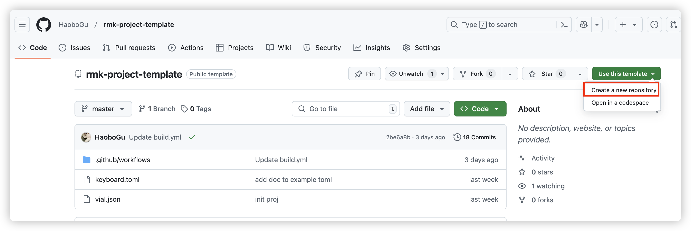
RMK provides a project-template that you can use to create your firmware easily. The following is a step-by-step tutorial for compiling RMK firmware using Github Actions.
Note: There are some limitations currently for cloud compilation. For example, you cannot edit cargo features in the generated project. If you have any problems when compiling RMK using cloud, please open an issue!
Steps
- To get started, open project-template, click
Use this templatebutton and chooseCreate a new repository:
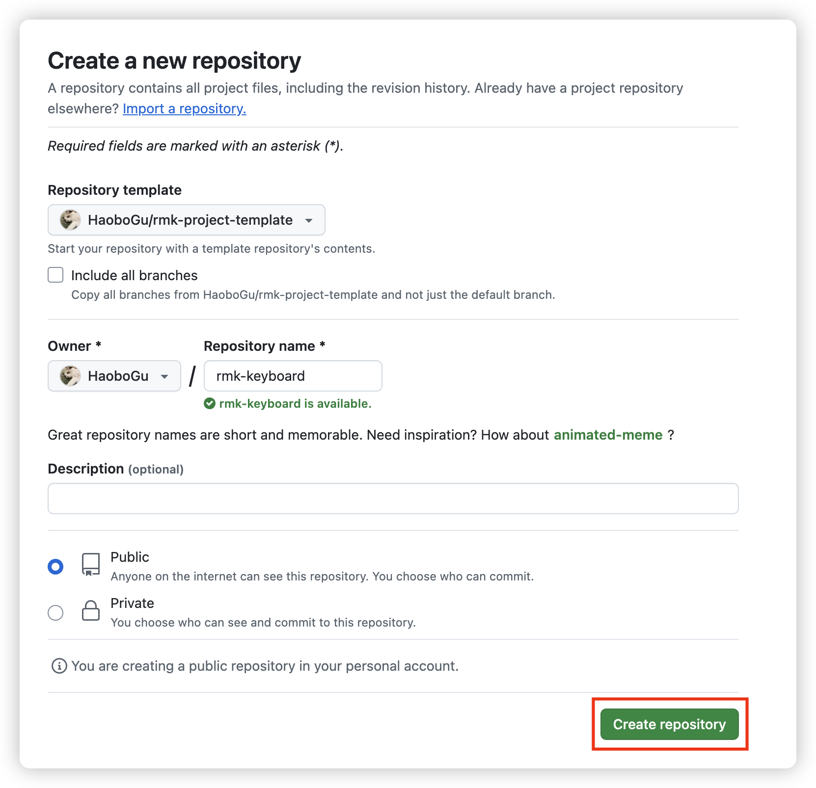
- Input your repository name, and click
Create repository
-
After the repository is created, there are two config files in the project:
keyboard.tomlandvial.json:keyboard.toml: this file defines almost everything about your keyboard, follow keyboard configuration to create your own keyboard definitionvial.json: this file contains matrix definitions which will be recognized by vial. RMK now uses vial to update the keymap on-the-fly. Follow vial's porting guide to createvial.jsonfor your keyboard.
you can edit the files directly on Github by clicking the file and then choosing
edit this file: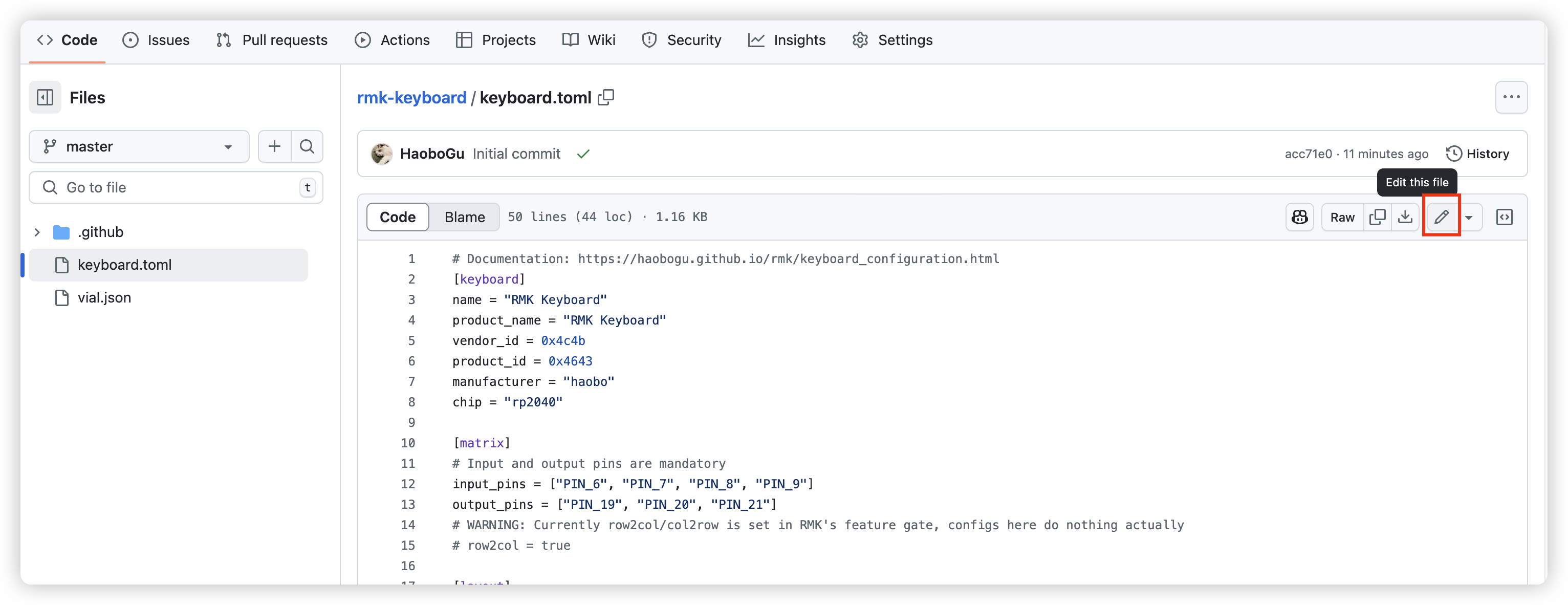 . After updating your config, click
 Commit changes..to save it: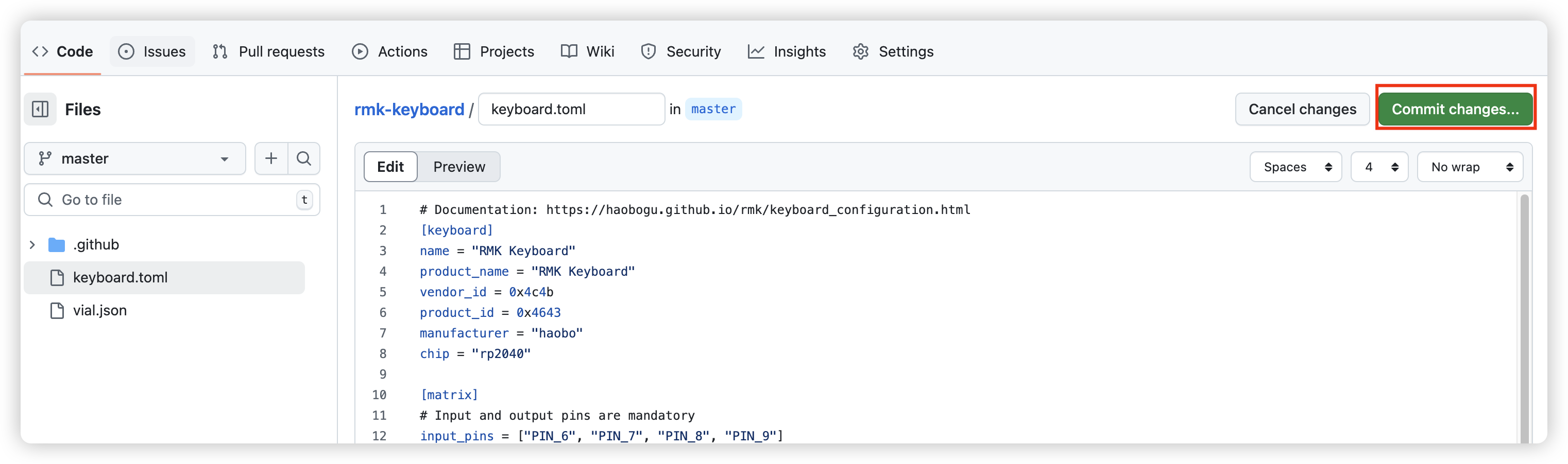
-
Once you saved your file, Github Action will automatically run to compile your firmware using your saved config files. Click
Actiontab on the top bar and you can see there's a workflow running.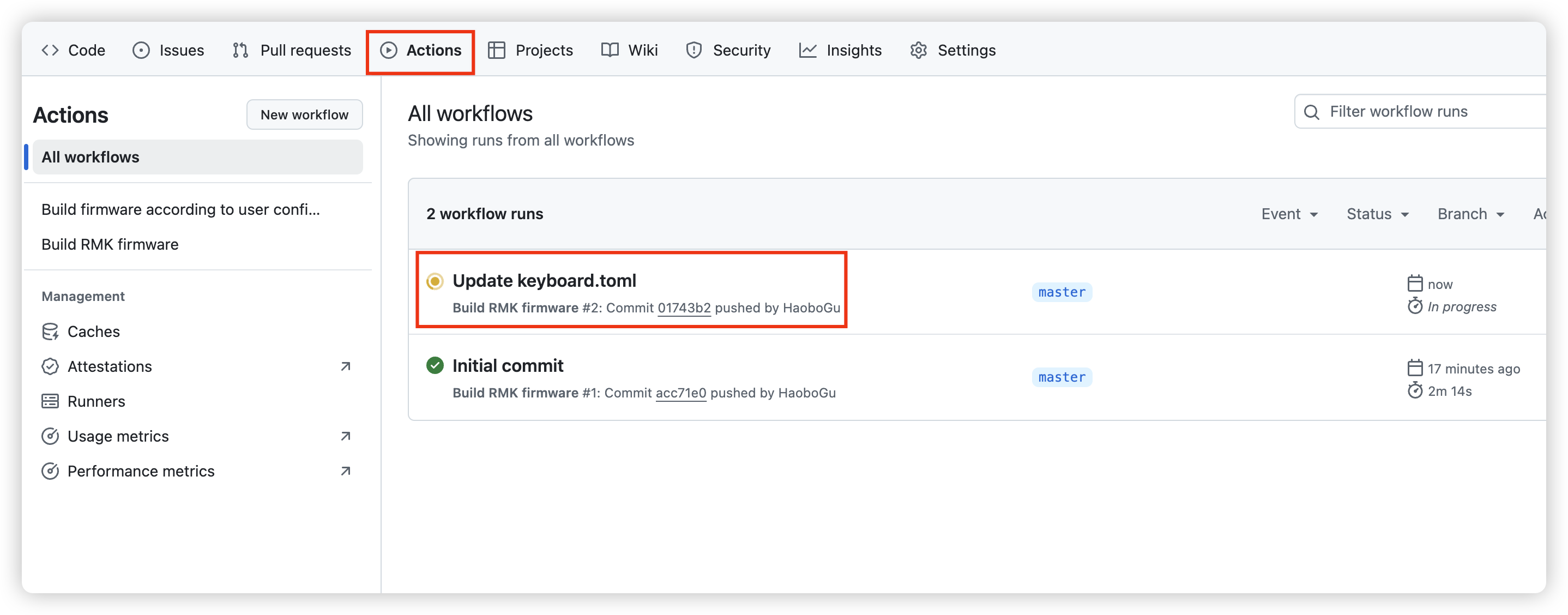
You can also check the compilation log by clicking
build/build. After the compilation finished, refresh the page and you can see the compiled RMK firmware underSummary/Artifacts: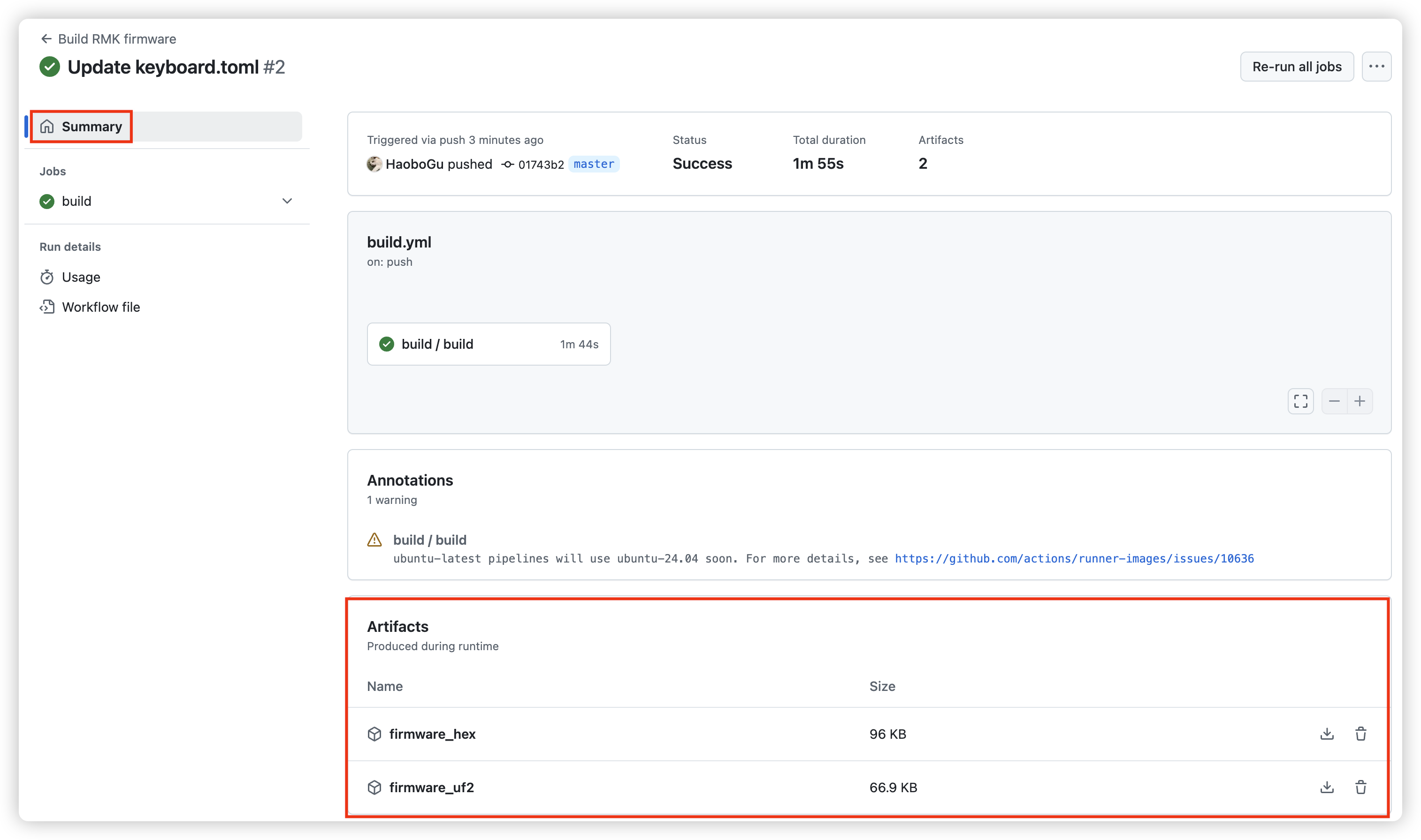
-
Now you get your RMK firmware! RMK provides
hexanduf2firmware that you can use. The final step is to flash the firmware to your microcontroller. Follow the instructions in Flash the firmware section.
Local compilation
This sections describes everything you need to compile RMK firmware on your local machine.
Setup RMK environment
First, you have to setup the Rust development environment and install all the needed components for compiling and flashing RMK.
1. Install Rust
Installing Rust is easy, checkout https://rustup.rs and follow the instructions.
Here is a more detailed guide for installing Rust.
2. Choose your hardware and install the target
RMK firmware runs on microcontrollers. By using Embassy as the runtime, RMK supports many series of microcontrollers, such as stm32, nrf52 and rp2040. Choosing one of the supported microcontrollers makes your journey of RMK much easier. In the RMK repo, there are many examples. The microcontrollers in the examples are safe options. If you're using other microcontrollers, make sure your microcontroller supports Embassy.
The next step is to add Rust's compilation target of your chosen microcontroller. Rust's default installation includes only your host's compilation target, so you have to install the compilation target of your microcontroller manually.
Different microcontrollers with different architectures may have different compilation targets. In case you're using ARM Cortex-M microcontrollers, here is a simple target list.
For example, rp2040 is a Cortex-M0+ microcontroller, it's compilation target is thumbv6m-none-eabi. Use rustup target add command to install it:
rustup target add thumbv6m-none-eabi
nRF52840 is also commonly used in wireless keyboards, it's compilation target is thumbv7em-none-eabihf. To add the target, run:
rustup target add thumbv7em-none-eabihf
3. Install rmkit and other tools
rmkit is a tool that helps you create your RMK project easily. You can use the following command to install rmkit:
cargo install rmkit
# If you have problems installing rmkit on Windows, try the following command to install it:
# powershell -ExecutionPolicy ByPass -c "irm https://github.com/haobogu/rmkit/releases/download/v0.0.9/rmkit-installer.ps1 | iex"
There are several other tools that should be installed:
-
flip-link: zero-cost stack overflow protection. -
cargo-make: used to automate uf2 generation. -
(optional)
probe-rs: used to flash and debug your firmware via debug proble. Here is the installation instruction.
You can use the following commands to install them:
  # Install flip-link
  cargo install flip-link cargo-make

  # Install probe-rs using scripts
  # Linux, macOS
  curl --proto '=https' --tlsv1.2 -LsSf https://github.com/probe-rs/probe-rs/releases/latest/download/probe-rs-tools-installer.sh | sh
  # Windows
  irm https://github.com/probe-rs/probe-rs/releases/latest/download/probe-rs-tools-installer.ps1 | iex
Create firmware project
You can use rmkit to create the firmware project:
rmkit init
This command will ask you to give some basic info about your project and then create a project from RMK's templates:
$ rmkit init
> Project Name: rmk-keyboard
> Choose your keyboard type? split
> Choose your microcontroller nrf52840
⇣ Download project template for nrf52840_split...
✅ Project created, path: rmk-keyboard
Now RMK has project templates for many microcontrollers, such as nRF52840, rp2040, stm32, esp32, etc. If you find that there's no template for your microcontroller, please feel free to add one.
Update firmware project
The generated project uses the keyboard.toml file to config the keyboard. These steps you have to do to customize your own firmware:
Edit keyboard.toml
The generated keyboard.toml should have some fields configured from rmkit init. But there are still some fields that you want to fill, such as the pin matrix, default keymap, led config, etc.
The Keyboard Configuration section has full instructions on how to write your own keyboard.toml. Follow the doc and report any issues/questions at https://github.com/HaoboGu/rmk/issues. We appreciate your feedback!
Update memory.x
memory.x is the linker script of the Rust embedded project, it's used to define the memory layout of the microcontroller. RMK enables the memory-x feature for embassy-stm32, so if you're using stm32, you can just ignore this step.
For other ARM Cortex-M microcontrollers, you only need to update the LENGTH of FLASH and RAM to your microcontroller.
If you're using nRF52840, ensure that you have Adafruit_nRF52_Bootloader flashed to your board. Most nice!nano compatible boards have it already. As long as you can open a USB drive for your board and update uf2 firmware by dragging and dropping, you're all set.
You can either checkout your microcontroller's datasheet or an existing Rust project of your microcontroller for it.
Add your own layout(vial.json)
The layout should be consistent with the default keymap set in
keyboard.toml
The next step is to add your own keymap layout for your firmware. RMK supports vial app, an open-source cross-platform(windows/macos/linux/web) keyboard configurator. So the vial like keymap definition has to be imported to the firmware project.
Fortunately, RMK does most of the heavy things for you, all you need to do is to create your own keymap definition and
convert it to vial.json following vial's doc here, and place it
at the root of the firmware project, replacing the default one. RMK will do all the rest for you.
(Optional) Update compilation target
For stm32 microcontrollers, the compilation target varies according to the series. If there's no project template for your specific stm32 model, a common template will be used. An extra step for the common template is to update .cargo/config.toml, change the project's default target:
[build]
# Pick ONE of these default compilation targets
# target = "thumbv6m-none-eabi"        # Cortex-M0 and Cortex-M0+
# target = "thumbv7m-none-eabi"        # Cortex-M3
# target = "thumbv7em-none-eabi"       # Cortex-M4 and Cortex-M7 (no FPU)
target = "thumbv7em-none-eabihf"     # Cortex-M4F and Cortex-M7F (with FPU)
# target = "thumbv8m.base-none-eabi"   # Cortex-M23
# target = "thumbv8m.main-none-eabi"   # Cortex-M33 (no FPU)
# target = "thumbv8m.main-none-eabihf" # Cortex-M33 (with FPU)
It's also welcome to submit and share your project template, please open an issue with your project attached.
Compile the firmware
Compiling the firmware is easy, just run
cargo build --release
If you've done all the previous steps correctly, you can find your compiled firmware at target/<your_target>/release folder, whose name is your project's name or the name set in Cargo.toml's [[bin]] section.
The firmware generated by Rust has no extension, which is actually an ELF file.
If you encountered any problems when compiling the firmware, please report it here.
Compile uf2 firmware
By default, Rust firmware is an ELF file, so we have to do some extra steps converting it to uf2 format.
RMK uses cargo-make to automate the uf2 firmware generation.
Then you should make sure the chip family argument(aka argument after --family) in Makefile.toml is correct. You can get your chip's family here.
That's all you need to set up. The final step is to run
cargo make uf2 --release
to generate your uf2 firmware.
Flash the firmware
The last step is to flash compiled firmware to your microcontroller. RMK supports flashing the firmware via uf2 bootloader or debug probe.
Use uf2 bootloader
Flashing using uf2 bootloader is easy: set your board to bootloader mode, then a USB drive should appear in your computer. Copy the uf2 firmware to the USB drive, and that's it!
If you're using macOS, an error might appear, you can safely ignore it.
Tips for nRF52840
For nRF52840, you need to check whether your have a UF2 bootloader flashed to your board. If you can enter bootloader mode, there will be an USB drive shown in your computer. If there's INFO_UF2.TXT in the USB drive, you have it! Then check the memory.x, ensure that the flash origin starts with 0x00001000:
MEMORY
{
  /* NOTE 1 K = 1 KiB = 1024 bytes */
  /* These values correspond to the nRF52840 WITH Adafruit nRF52 bootloader */
  FLASH : ORIGIN = 0x00001000, LENGTH = 1020K
  RAM : ORIGIN = 0x20000008, LENGTH = 255K

  /* These values correspond to the nRF52840 */
  /* FLASH : ORIGIN = 0x00000000, LENGTH = 1024K */
  /* RAM : ORIGIN = 0x20000000, LENGTH = 256K */
}
If you have a debug probe and don't want to use the bootloader, use the following memory.x config:
{
  /* NOTE 1 K = 1 KiB = 1024 bytes */
  /* These values correspond to the nRF52840 */
  FLASH : ORIGIN = 0x00000000, LENGTH = 1024K
  RAM : ORIGIN = 0x20000000, LENGTH = 256K
}
You can edit your memory.x to choose correct value for your bootloader.
Use debug probe
If you have a debug probe like daplink, jlink or stlink(stm32 only), things become much easier: connect it with your board and host, make sure you have installed probe-rs, then just run
cargo run --release
Then the command configured in .cargo/config.toml will be executed. The firmware will be flashed to your microcontroller and run automatically, yay!
For more configurations of RMK, you can check out feature documentations on the left.
FAQ
My matrix is row2col, the matrix doesn't work
RMK enables col2row as the default feature. To use the row2col matrix, you have to change your Cargo.toml, adds default-features = false to RMK crate, disabling the col2row feature.
# Cargo.toml
rmk = { version = "0.5", default-features = false, features = ["nrf52840_ble", "async_matrix"] }
If you're using the cloud compilation, you have to update your keyboard.toml, add row2col = true under the [matrix] section or [split.central.matrix] section:
# keyboard.toml
[matrix]
row2col = true

# Or
[split.central.matrix]
row2col = true
Where is my built firmware?
By default, the built firmware is at target/<TARGET>/<MODE> folder, where <TARGET> is your microcontroller's target and <MODE> is debug or release, depending on your build mode.
The firmware's name is your project name in Cargo.toml. It's actually an elf file, but without file extension.
I want hex/bin/uf2 file, how can I get it?
By default, Rust compiler generates elf file in target folder. There're a little extra steps for generating hex, bin or uf2 file.
-
hex/bin: To generatehex/binfile, you need cargo-binutils. You can usecargo install cargo-binutils rustup component add llvm-toolsto install it. Then, you can use the following command to generate
hexorbinfirmware:# Generate .bin file cargo objcopy --release -- -O binary rmk.bin # Generate .hex file cargo objcopy --release -- -O ihex rmk.hex -
uf2: RMK provides cargo-make config for all examples to generateuf2file automatically. CheckMakefile.tomlfiles in the example folders. The following command can be used to generate uf2 firmware:# Install cargo-make cargo install --force cargo-make # Generate uf2 cargo make uf2 --release
I changed keymap in keyboard.toml, but the keyboard is not updated
RMK assumes that users change the keymap using vial. So reflashing the firmware won't change the keymap by default. For testing senario, RMK provides a config clear_storage under [storage] section, you can enable it to clear the storage when the keyboard boots.
[storage]
# Set `clear_storage` to true to clear all the stored info when the keyboard boots
clear_storage = true
Note that the storage will be clear EVERYTIME you reboot the keyboard.
I can see a RMK Start log, but nothing else
First you need to check the RCC config of your board, make sure that the USB's clock is enabled and set to 48MHZ. For example, if you're using stm32f1, you can set the RCC as the following:
#![allow(unused)]
fn main() {
// If you're using a keyboard.toml
#[rmk_keyboard]
mod keyboard {
    use embassy_stm32::{time::Hertz, Config};

    #[Override(chip_config)]
    fn config() -> Config {
        let mut config = Config::default();
        config.rcc.hse = Some(Hse {
            freq: Hertz(8_000_000),
            // Oscillator for bluepill, Bypass for nucleos.
            mode: HseMode::Oscillator,
        });
        config.rcc.pll = Some(Pll {
            src: PllSource::HSE,
            prediv: PllPreDiv::DIV1,
            mul: PllMul::MUL9,
        });
        config.rcc.sys = Sysclk::PLL1_P;
        config.rcc.ahb_pre = AHBPrescaler::DIV1;
        config.rcc.apb1_pre = APBPrescaler::DIV2;
        config.rcc.apb2_pre = APBPrescaler::DIV1;
        config
    }
}
}
If the keyboard still doesn't work, enabling full logging trace at .cargo/config.toml:
[env]
DEFMT_LOG = "trace"
run cargo clean and then cargo run --release. Open an issue with the detailed logs.
rust-lld: error: section will not fit in region 'FLASH': overflowed by x bytes
This is because your MCU's flash is too small. Try building in release mode: cargo build --release. If the error still there, follow our binary size optimization doc to reduce your code size.
I see ERROR: Storage is full error in the log
By default, RMK uses only 2 sectors of your microcontroller's internal flash. You may get the following error if 2 sectors is not big enough to store all your keymaps:
ERROR Storage is full
└─ rmk::storage::print_sequential_storage_err @ /Users/haobogu/Projects/keyboard/rmk/rmk/src/storage.rs:577
ERROR Got none when reading keymap from storage at (layer,col,row)=(1,5,8)
└─ rmk::storage::{impl#2}::read_keymap::{async_fn#0} @ /Users/haobogu/Projects/keyboard/rmk/rmk/src/storage.rs:460
ERROR Keymap reading aborted!
└─ rmk::keymap::{impl#0}::new_from_storage::{async_fn#0} @ /Users/haobogu/Projects/keyboard/rmk/rmk/src/keymap.rs:38
If you have more sectors available in your internal flash, you can increase num_sectors in [storage] section of your keyboard.toml, or change storage_config in your RmkConfig if you're using Rust API.
panicked at embassy-executor: task arena is full.
The current embassy requires manually setting of the task arena size. By default, RMK set's it to 32768 in all examples:
# Cargo.toml
embassy-executor = { version = "0.7", features = [
    "defmt",
    "arch-cortex-m",
    "task-arena-size-32768",
    "executor-thread",
] }
If you got ERROR panicked at 'embassy-executor: task arena is full. error after flashing to your MCU, that means that you should increase your embassy's task arena. Embassy has a series cargo features to do this, for example, changing task arena size to 65536:
# Cargo.toml
embassy-executor = { version = "0.7", features = [
    "defmt",
    "arch-cortex-m",
-   "task-arena-size-32768",
+   "task-arena-size-65536",
    "executor-thread",
] }
In the latest git version of embassy, task arena size could be calculated automatically, but it requires nightly version of Rust.
If you're comfortable with nightly Rust, you can enable nightly feature of embassy-executor and remove task-arena-size-* feature.
RMK breaks my bootloader
By default RMK uses last 2 sectors as the storage. If your bootloader is placed there too, RMK will erase it. To avoid it, you can change start_addr in [storage] section of your keyboard.toml, or change storage_config in your RmkConfig if you're using Rust API.
What font is used for the RMK logo?
It's Honk.
Real world examples
This pages contains real world examples of RMK keyboards.
rmk-ble-keyboard
A BLE/USB dual-mode GH60 keyboard using Ebyte's E73 nRF52840 module.
dactyl-lynx-rmk
Show your keyboard!
If you're using RMK to build your keyboard, feel free to open a PR adding your project to this page!
Configuration
RMK provides an easy and accessible way to set up the keyboard with a toml config file, even without Rust code!
Usage
A toml file named keyboard.toml is used as the configuration file of RMK. The following is the spec of toml if you're unfamiliar with toml:
RMK provides a proc-macro to load the keyboard.toml at your projects root: #[rmk_keyboard], add it to your main.rs like:
#![allow(unused)]
fn main() {
use rmk::macros::rmk_keyboard;

#[rmk_keyboard]
mod my_keyboard {}
}
And, that's it! The #[rmk_keyboard] macro would load your keyboard.toml config and create everything that's needed for creating a RMK keyboard instance.
If you don't want any other customizations beyond the keyboard.toml, #[rmk_keyboard] macro will just work. For the examples, please check the example/use_config folder.
What's in the config file?
The config file contains almost EVERYTHING to customize a keyboard. For the full reference of keyboard.toml, please refer to this doc. Also, we have pre-defined default configurations for chips, at rmk-macro/src/default_config folder. We're going to add default configurations for more chips, contributions are welcome!
The following are the available tables and related documentaion available in keyboard.toml:
- Keyboard and matrix: basic information and physical key matrix definition of the keyboard
- Layout: layout and default keymap configuration of the keyboard
- Split keyboard: split keyboard configuration
- Storage: configuration for storage, which is used for on-board config and keymap
- Behavior: configuration for advanced keyboard behaviors, such as one-shot key, tri-layer, tap-hold(including HRM mode), etc.
- Input device: configuration for input devices, such as rotary encoder, joystick, etc.
- Wireless/Bluetooth: configuration for wireless/bluetooth
- Light: configuration for lights
- RMK config: internal configurations of RMK, such as length of communication channels, number of allowed macros, etc
- Appendix: full spec and references of the
keyboard.toml
TODOs:
- read vial.json and check whether vial.json is consist of keyboard.toml
Keyboard and matrix
[keyboard]
[keyboard] section contains basic information of the keyboard, such as keyboard's name, chip, etc:
[keyboard]
name = "RMK Keyboard"
vendor_id = 0x4c4b
product_id = 0x4643
manufacturer = "RMK"
chip = "stm32h7b0vb"
# If your chip doesn't have a functional USB peripheral, for example, nRF52832/esp32c3(esp32c3 has only USB serial, not full functional USB), set `usb_enable` to false
usb_enable = true
[matrix]
[matrix] section defines the physical key matrix IO information of the keyboard, aka input/output pins.
Key matrix
For the normal key matrix, in order to identify the IO pins take a look at your keyboard's schematic: The pin going to the diode (called anode) is an output pin, the pin coming out (called cathode) is an input pin:
output_pin =>   >|   => input_pin
                 ↑
              diode(be aware of it's direction)
IO pins are represented with an array of string, the string value should be the GPIO peripheral name of the chip. For example, if you're using stm32h750xb, you can go to https://docs.embassy.dev/embassy-stm32/git/stm32h750xb/peripherals/index.html to get the valid GPIO peripheral name:
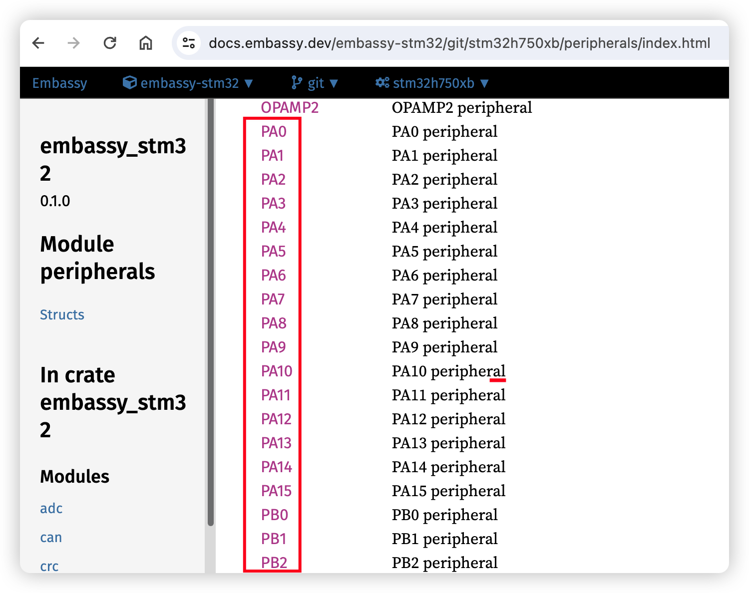
The GPIO peripheral name varies for different chips. For example, RP2040 has PIN_0, nRF52840 has P0_00 and stm32 has PA0. So it's recommended to check the embassy's doc for your chip to get the valid GPIO name first.
Here is an example toml of [matrix] section for stm32:
[matrix]
# Input and output pins are mandatory
input_pins = ["PD4", "PD5", "PD6", "PD3"]
output_pins = ["PD7", "PD8", "PD9"]
# WARNING: Currently row2col/col2row is set in RMK's feature gate, row2col config here is valid ONLY when you're using cloud compilation
# row2col = true
Direct pins
If your keys are directly connected to the microcontroller pins, set matrix_type to direct_pin. (The default value for matrix_type is normal)
direct_pins is a two-dimensional array that represents the physical layout of your keys.
If your pin requires a pull-up resistor and the button press pulls the pin low, set direct_pin_low_active to true. Conversely, set it to false if your pin requires a pull-down resistor and the button press pulls the pin high.
Here is an example for rp2040.
matrix_type = "direct_pin"
direct_pins = [
    ["PIN_0", "PIN_1", "PIN_2"],
    ["PIN_3", "_", "PIN_5"]
]
# `direct_pin_low_active` is optional. Default to `true`.
direct_pin_low_active = true
Layout
[layout]
[matrix] defines the physical key matrix on your board, while [layout] section contains the layout and the default keymap for the keyboard:
[layout]
rows = 5
cols = 4
layers = 3
matrix_map = """
    ... the mapping between the "electronic matrix" of your keyboard
        and your key map configuration is described here ...
"""
The matrix_map is a string built from (row, col) coordinate pairs, listed in the same order as you want to define your keys in your key map. The (row, col) coordinates are using zero based indexing and referring to the position in the "electronic matrix" of your keyboard. As you can see in matrix configuration, even the direct pin based keyboards are represented with a matrix. In case of split keyboards, the positions refer to the position in the "big unified matrix" of all split parts.
With the help of this matrix map, the configuration of non-regular key matrices can be intuitively arranged in your key maps.
(Triple quote mark """ is used to limit multi-line strings
# ┌───┬───┬───┬───┐
# │NUM│ / │ * │ - │ <-- row 0, col 0..4
# ├───┼───┼───┼───┤
# │ 7 │ 8 │ 9 │   │
# ├───┼───┼───┤ + │
# │ 4 │ 5 │ 6 │   │
# ├───┼───┼───┼───┤
# │ 1 │ 2 │ 3 │ E │
# ├───┴───┼───┤ N │
# │   0   │ . │ T │
# └───────┴───┴───┘
[layout]
rows = 5
cols = 4
layers = 3
matrix_map = """
(0,0) (0,1) (0,2) (0,3)
(1,0) (1,1) (1,2) (1,3)
(2,0) (2,1) (2,2)
(3,0) (3,1) (3,2) (3,3)
   (4,0)    (4,1)
"""
Once the layout is defined, the key mapping can be described for each layer:
# layer 0 (default):
[[layer]]
name = "base_layer" #optional name for the layer
keys = """
NumLock KpSlash KpAsterisk KpMinus
Kp7     Kp8     Kp9        KpPlus
Kp4     Kp5     Kp6
Kp1     Kp2     Kp3        Enter
    Kp0         KpDot
"""

# layer 1:
[[layer]]
name = "mouse_navigation" #optional name for the layer
keys = """
TO(base_layer)   @my_cut    @my_copy         @my_paste
MouseBtn1        MouseUp    MouseBtn2        MouseWheelUp
MouseLeft        MouseBtn4  MouseRight
MouseWheelLeft   MouseDown  MouseWheelRight  MouseWheelDown
       MouseBtn1            MouseBtn12
"""
The number and order of entries on each defined layers must be identical with the number and order of entries in matrix_map.
White spaces, line breaks are free to vary, but its worth to keep a consistent arrangement with the real keyboard.
In each layer.keys, the keys are bound to various key actions. Due to the limitation of toml file, this is done in a string.
RMK parses the string and fill the to actual keymap initializer, like what's in keymap.rs
The layer.keys string should follow several rules:
-
For a simple keycode(aka keys in RMK's
KeyCodeenum), just fill its name.For example, if you set a keycode
Backspace, it will be turned toKeyCode::Backspace. So you have to ensure that the keycode string is valid, or RMK wouldn't compile! However, to make things easier a number of alternative key names were added and also case-insensitive search is used to find the valid KeyCode.For simple keycodes with modifiers active, you can use
WM(key, modifier)to create a keypress with modifier action. Modifiers can be chained together likeLShift | RGuito have multiple modifiers active.You may use aliases, prefixed with
@, like@my_copyin the above example. The alias names are case sensitive. The definition of aliases is described below.You may use layer names instead of layer numbers, like
TO(base_layer)in the above example.Please note that layer name if used like this, may not contain white spaces and may not be a number. Layer names are case sensitive. -
For no-key (
KeyAction::No), useNo -
For transparent key (
KeyAction::Transparent), use_or__(you can put any number of_) -
RMK supports many advanced layer operations:
- Use
DF(n)to create a switch default layer action,nis the layer number - Use
MO(n)to create a layer activate action,nis the layer number - Use
LM(n, modifier)to create layer activate with modifier action. The modifier can be chained in the same way asWM - Use
LT(n, key)to create a layer activate action or tap key(tap/hold). Thekeyhere is the RMKKeyCode - Use
OSL(n)to create a one-shot layer action,nis the layer number - Use
OSM(modifier)to create a one-shot modifier action. The modifier can be chained in the same way asWM - Use
TT(n)to create a layer activate or tap toggle action,nis the layer number - Use
TG(n)to create a layer toggle action,nis the layer number - Use
TO(n)to create a layer toggle only action (activate layernand deactivate all other layers),nis the layer number
- Use
The definitions of those operations are same with QMK, you can found here. If you want other actions, please fire an issue.
-
For modifier-tap-hold, use
MT(key, modifier)where the modifier can be a chain like explained on point 1. For example for a Home row modifier config you can useMT(F, LShift) -
For generic key tap-hold, use
TH(key-tap, key-hold) -
For shifted key, use
SHIFTED(key)
[aliases]
[aliases] section contains a table of user defined names and an associated replacement string, which can be used in the layer.keys:
# here are the aliases for the example above
[aliases]
my_cut = "WM(X, LCtrl)"
my_copy = "WM(C, LCtrl)"
my_paste = "WM(V, LCtrl)"
Split keyboard
See Split Keyboard section
Storage
[storage]
[storage] section defines storage related configs. Storage feature is required to persist keymap data, it's strongly recommended to make it enabled(and it's enabled by default!). RMK will automatically use the last two section of chip's internal flash as the pre-served storage space. For some chips, there's also predefined default configuration, such as nRF52840. If you don't want to change the default setting, just ignore this section.
[storage]
# Storage feature is enabled by default
enabled = true
# Start address of local storage, MUST BE start of a sector.
# If start_addr is set to 0(this is the default value), the last `num_sectors` sectors will be used.
start_addr = 0x00000000
# How many sectors are used for storage, the default value is 2
num_sectors = 2
Behavior
[behavior]
[behavior] section contains configuration for how different keyboard actions should behave:
[behavior]
tri_layer = { uppper = 1, lower = 2, adjust = 3 }
one_shot = { timeout = "1s" }
Tri Layer
Tri Layer works by enabling a layer (called adjust) when other two layers (upper and lower) are both enabled.
You can enable Tri Layer by specifying the upper, lower and adjust layers in the tri_layer sub-table:
[behavior.tri_layer]
uppper = 1
lower = 2
adjust = 3
In this example, when both layers 1 (upper) and 2 (lower) are active, layer 3 (adjust) will also be enabled.
Note that "#layer_name" could also be used in place of layer numbers.
Tap Hold
In the tap_hold sub-table, you can configure the following parameters:
enable_hrm: Enables or disables HRM (Home Row Mod) mode. When enabled, theprior_idle_timesetting becomes functional. Defaults tofalse.prior_idle_time: If the previous non-modifier key is released within this period before pressing the current tap-hold key, the tap action for the tap-hold behavior will be triggered. This parameter is effective only when enable_hrm is set totrue. Defaults to 120ms.hold_timeout: Defines the duration a tap-hold key must be pressed to determine hold behavior. If tap-hold key is released within this time, the key is recognized as a "tap". Holding it beyond this duration triggers the "hold" action. Defaults to 250ms.post_wait_time: Adds an additional delay after releasing a tap-hold key to check if any keys pressed during thehold_timeoutare released. This helps accommodate fast typing scenarios where some keys may not be fully released during a hold. Defaults to 50ms
The following are the typical configurations:
[behavior]
# Enable HRM
tap_hold = { enable_hrm = true, prior_idle_time = "120ms", hold_timeout = "250ms", post_wait_time = "50ms"}
# Disable HRM, you can safely ignore any fields if you don't want to change them
tap_hold = { enable_hrm = false, hold_timeout = "200ms" }
One Shot
In the one_shot sub-table you can define how long OSM or OSL will wait before releasing the modifier/layer with the timeout option, default is one second.
timeout is a string with a suffix of either "s" or "ms".
[behavior.one_shot]
timeout = "5s"
Combo
In the combo sub-table, you can configure the keyboard's combo key functionality. Combo allows you to define a group of keys that, when pressed simultaneously, will trigger a specific output action.
Combo configuration includes the following parameters:
timeout: Defines the maximum time window for pressing all combo keys. If the time exceeds this, the combo key will not be triggered. The format is a string, which can be milliseconds (e.g. "200ms") or seconds (e.g. "1s").combos: An array containing all defined combos. Each combo configuration is an object containing the following attributes:actions: An array of strings defining the keys that need to be pressed simultaneously to trigger the combo action.output: A string defining the output action to be triggered when all keys inactionsare pressed simultaneously.layer: An optional parameter, a number, specifying which layer the combo is valid on. If not specified, the combo is valid on all layers.
Here is an example of combo configuration:
[behavior.combo]
timeout = "150ms"
combos = [
  # Press J and K keys simultaneously to output Escape key
  { actions = ["J", "K"], output = "Escape" },
  # Press F and D keys simultaneously to output Tab key, but only valid on layer 0
  { actions = ["F", "D"], output = "Tab", layer = 0 },
  # Three-key combo, press A, S, and D keys to switch to layer 2
  { actions = ["A", "S", "D"], output = "TO(2)" }
]
Fork
In the fork sub-table, you can configure the keyboard's state based key fork functionality. Forks allows you to define a trigger key and condition dependent possible replacement keys. When the trigger key is pressed, the condition is checked by the following rule:
If any of the match_any states are active AND none of the match_none states active, the trigger key will be replaced with positive_output, otherwise with the negative_output. By default the modifiers listed in match_any will be suppressed (even the one-shot modifiers) for the time the replacement key action is executed. However, with kept_modifiers some of them can be kept instead of automatic suppression.
Fork configuration includes the following parameters:
forks: An array containing all defined forks. Each fork configuration is an object containing the following attributes:trigger: Defines the triggering key.negative_output: A string defining the output action to be triggered when the conditions are not metpositive_output: A string defining the output action to be triggered when the conditions are metmatch_any: A strings defining a combination of modifier keys, lock leds, mouse buttons (optional)match_none: A strings defining a combination of modifier keys, lock leds, mouse buttons (optional)kept_modifiers: A strings defining a combination of modifier keys, which should not be 'suppressed' form the keyboard state for the time the replacement action is executed. (optional)bindable: Enables the evaluation of not yet triggered forks on the output of this fork to further manipulate the output. Advanced use cases can be solved using this option. (optional)
For match_any, match_none the legal values are listed below (many values may be combined with "|"):
LShift,LCtrl,LAlt,LGui,RShift,RCtrl,RAlt,RGui(these are including the effect of explicitly held and one-shot modifiers too)CapsLock,ScrollLock,NumLock,Compose,KanaMouseBtn1..MouseBtn8
Here is a sample of fork configuration with random examples:
[behavior.fork]
forks = [
  # Shift + '.' output ':' key
  { trigger = "Dot", negative_output = "Dot", positive_output = "WM(Semicolon, LShift)", match_any = "LShift|RShift" },

  # Shift + ',' output ';' key but only if no Alt is pressed
  { trigger = "Comma", negative_output = "Comma", positive_output = "Semicolon", match_any = "LShift|RShift", match_none = "LAlt|RAlt" },

  # left bracket outputs by default '{', with shifts pressed outputs '['
  { trigger = "LeftBracket", negative_output = "WM(LeftBracket, LShift)", positive_output = "LeftBracket", match_any = "LShift|RShift" },

  # Flip the effect of shift on 'x'/'X'
  { trigger = "X", negative_output = "WM(X, LShift)", positive_output = "X", match_any = "LShift|RShift" },

  # F24 usually outputs 'a', except when Left Shift or Ctrl pressed, in that case triggers a macro
  { trigger = "F24", negative_output = "A", positive_output = "Macro1", match_any = "LShift|LCtrl" },

  # Swap Z and Y keys if MouseBtn1 is pressed (on the keyboard) (Note that these must not be bindable to avoid infinite fork loops!)
  { trigger = "Y", negative_output = "Y", positive_output = "Z", match_any = "MouseBtn1", bindable = false },
  { trigger = "Z", negative_output = "Z", positive_output = "Y", match_any = "MouseBtn1", bindable = false },

  # Shift + Backspace output Delete key (inside a layer tap/hold)
  { trigger = "LT(2, Backspace)", negative_output = "LT(2, Backspace)", positive_output = "LT(2, Delete)", match_any = "LShift|RShift" },

  # Ctrl + play/pause will send next track. MediaPlayPause -> MediaNextTrack
  # Ctrl + Shift + play/pause will send previous track. MediaPlayPause -> MediaPrevTrack
  # Alt + play/pause will send volume up. MediaPlayPause -> AudioVolUp
  # Alt + Shift + play/pause will send volume down. MediaPlayPause -> AudioVolDown
  # Ctrl + Alt + play/pause will send brightness up. MediaPlayPause -> BrightnessUp
  # Ctrl + Alt + Shift + play/pause will send brightness down. MediaPlayPause -> BrightnessDown
  # ( Note that the trigger and immediate trigger keys of the fork chain could be 'virtual keys',
  #   which will never output, like F23, but here multiple overrides demonstrated.)
    { trigger = "MediaPlayPause", negative_output = "MediaPlayPause", positive_output = "MediaNextTrack", match_any = "LCtrl|RCtrl", bindable = true },
  { trigger = "MediaNextTrack", negative_output = "MediaNextTrack", positive_output = "BrightnessUp", match_any = "LAlt|RAlt", bindable = true },
  { trigger = "BrightnessUp", negative_output = "BrightnessUp", positive_output = "BrightnessDown", match_any = "LShift|RShift", bindable = false },
  { trigger = "MediaNextTrack", negative_output = "MediaNextTrack", positive_output = "MediaPrevTrack", match_any = "LShift|RShift", match_none = "LAlt|RAlt", bindable = false},
  { trigger = "MediaPlayPause", negative_output = "MediaPlayPause", positive_output = "AudioVolUp", match_any = "LAlt|RAlt", match_none = "LCtrl|RCtrl", bindable = true },
  { trigger = "AudioVolUp", negative_output = "AudioVolUp", positive_output = "AudioVolDown", match_any = "LShift|RShift", match_none = "LCtrl|RCtrl", bindable = false }
]
Please note that the processing of forks happen after combos and before others, so the trigger key must be the one listed in your keymap (or combo output).
For example if LT(2, Backspace) is in your keymap, then trigger = "Backspace" will NOT work, you should "replace" the full key and use trigger = "LT(2, Backspace)" instead, like in the example above.
You may want to include F24 or similar dummy keys in your keymap, and use them as trigger for your pre-configured forks, such as Shift/CapsLock dependent macros to enter unicode characters of your language.
Vial does not support fork configuration yet.
Input devices
All input devices are defined in the [input_device] table. Currently supported input device types include:
- Rotary Encoder (encoder)
- Joystick (joystick)
Rotary Encoder(not ready yet)
A rotary encoder is a common input device that can be used for volume control, page scrolling, and other functions. It can be defined in the configuration file as follows:
[[input_device.encoder]]
pin_a = "P0_30"
pin_b = "P0_31"

# Working mode of the encoder
# Available modes:
# - default: EC11 compatible mode, resolution = 1
# - e8h7: resolution = 2, direction reversed
# - resolution: custom resolution, requires specifying resolution and reverse parameters
phase = "default"

# Resolution represents the number of pulses generated per detent
# For example: if your encoder has 30 detents and generates 15 pulses per 360-degree rotation, then resolution = 30/15 = 2
# The number of detents and pulses can be found in your encoder's datasheet
resolution = 2

# Whether to reverse the encoder direction
reverse = false
Multiple encoders can be added, and their indices are determined by the order of addition:
# Encoder 0
[[input_device.encoder]]
pin_a = "P0_01"
pin_b = "P0_02"
phase = "default"

# Encoder 1
[[input_device.encoder]]
pin_a = "P0_03"
pin_b = "P0_04"
phase = "default"
Joystick
A joystick is an analog input device that can be used for mouse control and other functions. Currently only NRF series chips are supported.
[[input_device.joystick]]
name = "default"
pin_x = "P0_31"
pin_y = "P0_29"
pin_z = "_"
transform = [[80, 0], [0, 80]]
bias = [29130, 29365]
resolution = 6
Parameters:
name: Unique name for the joystick. If you have multiple joysticks, they need different namespin_x: Pin for X-axispin_y: Pin for Y-axispin_z: Pin for Z-axistransform: Transformation matrix for the joystickbias: Bias value for each axisresolution: Resolution for each axis
Axis Configuration Note:
_indicates that the axis does not exist.
_is only allowed for:
- Both y and z axes are missing
- Only z axis is missing
For example:
pin_x = "_"pin_y = "P0_29"pin_z = "P0_30"is not allowed
Working Principle
-
Device reads values from each axis
-
Adds
biasvalue to each axis to make the value close to 0 when the joystick is released -
About the
transformmatrix:- New x-axis value = (axis_x + bias[0]) / transform[0][0] + (axis_y + bias[1]) / transform[0][1] + (axis_z + bias[2]) / transform[0][2]
- New y-axis value = (axis_x + bias[0]) / transform[1][0] + (axis_y + bias[1]) / transform[1][1] + (axis_z + bias[2]) / transform[1][2]
- New z-axis value = (axis_x + bias[0]) / transform[2][0] + (axis_y + bias[1]) / transform[2][1] + (axis_z + bias[2]) / transform[2][2]
If
transform[new_axis][old_axis]is 0, that old axis value is ignored.Since the value range read by the ADC device is usually much larger than the mouse report range of -256~255,
transformis designed as a divisor. -
Each axis value is adjusted to the largest integer multiple of
resolutionthat is less than its original value to reduce noise from ADC device readings.
Quick Configuration Guide
-
First set
biasto 0,resolutionto 1, andtransformto[[1, 0, 0], [0, 1, 0], [0, 0, 1]](matrix dimension depends on the number of axes) -
Find the optimal
biasvalue:- Use a debug probe to find the output
JoystickProcessor::generate_report: record = [axis_x, axis_y, axis_z]in debug information - Observe these values to find the
biasvalue that makes each axis closest to 0 when the joystick is released
- Use a debug probe to find the output
-
If the mouse moves too fast, gradually increase the
transformvalue until you find the right sensitivity -
If the mouse jitters, gradually increase the
resolutionvalue until the jitter disappears
Pointing Device(Draft, not implemented)
Pointing devices (such as touchpads) can be connected via I2C or SPI interface. Configuration examples:
[[input_device.pointing]]
interface = { i2c = { instance = "TWIM0", scl = "P0_27", sda = "P0_26" } }
or
[[input_device.pointing]]
interface = { spi = { instance = "SPIM0", sck = "P0_25", mosi = "P0_24", miso = "P0_23", cs = "P0_22", cpi = 1000 } }
Parameters:
I2C Configuration
instance: I2C instance namescl: Clock pinsda: Data pin
SPI Configuration
instance: SPI instance namesck: Clock pinmosi: Master Out Slave In pinmiso: Master In Slave Out pincs: Chip Select pin (optional)cpi: Counts Per Inch (optional)
Wireless/Bluetooth
[ble]
To enable BLE, add enabled = true under the [ble] section.
There are several more configs for reading battery level and charging state, now they are available for nRF52840 only.
# Ble configuration
# To use the default configuration, ignore this section completely
[ble]
# Whether to enable BLE feature
enabled = true
# nRF52840's saadc pin for reading battery level, you can use a pin number or "vddh"
battery_adc_pin = "vddh"
# The voltage divider setting for saadc.
# For example, nice!nano have 806 + 2M resistors, the saadc measures voltage on 2M resistor, so the two values should be set to 2000 and 2806
adc_divider_measured = 2000
adc_divider_total = 2806
# Pin that reads battery's charging state, `low-active` means the battery is charging when `charge_state.pin` is low
charge_state = { pin = "PIN_1", low_active = true }
# Output LED pin that blinks when the battery is low
charge_led= { pin = "PIN_2", low_active = true }
Light
[light]
[light] section defines lights of the keyboard, aka capslock, scrolllock and numslock. They are actually an input pin, so there are two fields available: pin and low_active.
pin field is just like IO pins in [matrix], low_active defines whether the light low-active or high-active(true means low-active).
You can safely ignore any of them, or the whole [light] section if you don't need them.
[light]
capslock = { pin = "PIN_0", low_active = true }
scrolllock = { pin = "PIN_1", low_active = true }
numslock= { pin = "PIN_2", low_active = true }
RMK Internal Configuration
The [rmk] section defines configuration parameters used inside RMK. These parameters affect the firmware's behavior, memory usage, and performance. If you don't need to change these parameters, you can ignore this section.
Configuration Example
[rmk]
# Mouse key interval (ms) - controls mouse movement speed
mouse_key_interval = 20
# Mouse wheel interval (ms) - controls scrolling speed
mouse_wheel_interval = 80
# Maximum number of combos keyboard can store
combo_max_num = 8
# Maximum number of keys pressed simultaneously in a combo
combo_max_length = 4
# Maximum number of forks for conditional key actions
fork_max_num = 8
# Macro space size in bytes for storing sequences. The maximum number of Macros depends on the size of each sequence: All sequences combined need to fit into macro_space_size, the number of macro sequences doesn't matter.
macro_space_size = 256
# Default debounce time in ms
debounce_time = 20
# Event channel size
event_channel_size = 16
# Report channel size
report_channel_size = 16
# Vial channel size
vial_channel_size = 4
# Flash channel size
flash_channel_size = 4
# The number of the split peripherals
split_peripherals_num = 1
# The size of the split message channel
split_message_channel_size = 4
# The number of available BLE profiles
ble_profiles_num = 3
Parameter Details
Mouse-Related Configuration
mouse_key_interval: Mouse key interval in milliseconds, default value is 20. This parameter controls the mouse movement speed; lower values result in faster movement.mouse_wheel_interval: Mouse wheel interval in milliseconds, default value is 80. This parameter controls the scrolling speed; lower values result in faster scrolling.
Behavior Configuration
NOTE: Increasing the number of combos, forks and macros will increase memory usage.
combo_max_num: Maximum number of combos that the keyboard can store, default value is 8. This value must be between 0 and 256.combo_max_length: Maximum number of keys that can be pressed simultaneously in a combo, default value is 4.fork_max_num: Maximum number of forks for conditional key actions, default value is 8. This value must be between 0 and 256.macro_space_size: Space size in bytes for storing macro sequences, default value is 256.
Matrix Configuration
debounce_time: Default key debounce time in milliseconds, default value is 20.
Channel Configuration
In RMK there are several channels used for communication between tasks. The length of the channel can be adjusted. Larger channel size means more events can be buffered, but it will increase memory usage.
event_channel_size: The length of event channel, default value is 16.report_channel_size: The length of report channel, default value is 16.vial_channel_size: The length of vial channel, default value is 4.flash_channel_size: The length of flash channel, default value is 4.
Split Keyboard Configuration
split_peripherals_num: The number of split peripherals, default value is 1.split_message_channel_size: The length of the split message channel, default value is 4.
Wireless Configuration
ble_profiles_num: The number of available Bluetooth profiles, default value is 3. This parameter defines how many Bluetooth paired devices the keyboard can store.
Appendix
keyboard.toml
The following toml contains all available settings in keyboard.toml
# Basic info of the keyboard
[keyboard]
name = "RMK Keyboard" # Keyboard name
product_name = "RMK Keyboard" # Display name of this keyboard
vendor_id = 0x4c4b
product_id = 0x4643
manufacturer = "haobo"
serial_number = "vial:f64c2b3c:000001"
# The chip or existing board used in keyboard
# Either \"board\" or \"chip\" can be set, but not both
chip = "rp2040"
board = "nice!nano_v2"
# USB is enabled by default for most chips
# Set to false if you don't want USB
usb_enable = true

# Set matrix IO for the board. This section is for non-split keyboard and is conflict with [split] section
[matrix]
# `matrix_type` is optional. Default is "normal"
matrix_type = "normal"
# Input and output pins
input_pins = ["PIN_6", "PIN_7", "PIN_8", "PIN_9"]
output_pins = ["PIN_19", "PIN_20", "PIN_21"]
# WARNING: Currently row2col/col2row is set in RMK's feature gate, row2col config here is valid ONLY when you're using cloud compilation

# Direct Pin Matrix is a Matrix of buttons connected directly to pins. It conflicts with the above.
matrix_type = "direct_pin"
direct_pins = [
    ["PIN_0", "PIN_1", "PIN_2"],
    ["PIN_3", "_", "PIN_5"]
]

# `direct_pin_low_active` is optional. Default is `true`.
# If your pin needs to be pulled up and the pin is pulled down when the button is turned on, please set it to true
# WARNING: If you use a normal matrix, it will be ineffective
direct_pin_low_active = true

# Layout info for the keyboard, this section is mandatory
[layout]
# Number of rows. For split keyboard, this is the total rows contains all splits
rows = 5
# Number of cols. For split keyboard, this is the total cols contains all splits
cols = 4
# Number of layers. Be careful, since large layer number takes more flash and RAM
layers = 3
# keypad example:
# ┌───┬───┬───┬───┐
# │NUM│ / │ * │ - │ <-- row 0, col 0..4
# ├───┼───┼───┼───┤
# │ 7 │ 8 │ 9 │   │
# ├───┼───┼───┤ + │
# │ 4 │ 5 │ 6 │   │
# ├───┼───┼───┼───┤
# │ 1 │ 2 │ 3 │ E │
# ├───┴───┼───┤ N │
# │   0   │ . │ T │
# └───────┴───┴───┘
matrix_map = """
(0,0) (0,1) (0,2) (0,3)
(1,0) (1,1) (1,2) (1,3)
(2,0) (2,1) (2,2)
(3,0) (3,1) (3,2) (3,3)
(4,0)       (4,1)
"""

# here are the aliases for the example layer.keys below
[aliases]
my_cut = "WM(X, LCtrl)"
my_copy = "WM(C, LCtrl)"
my_paste = "WM(V, LCtrl)"

# Key map definitions per layer:
# The number (and order) of entries on each layer should be
# identical with the number (and order) of entries in `matrix_map`.
# Empty layers will be used to fill if the number of explicitly
# defined layers is smaller then `layout.layers` setting

# layer 0 (default):
# (the number comes from the order of '[[layer]] entries' in the file)
[[layer]]
name = "base_layer" #optional name for the layer
keys = """
NumLock KpSlash KpAsterisk KpMinus
Kp7     Kp8     Kp9        KpPlus
Kp4     Kp5     Kp6
Kp1     Kp2     Kp3        Enter
    Kp0         KpDot
"""

# layer 1:
[[layer]]
name = "mouse_navigation" #optional name for the layer
keys = """
TO(base_layer)   @MyCut     @MyCopy          @MyPaste
MouseBtn1        MouseUp    MouseBtn2        MouseWheelUp
MouseLeft        MouseBtn4  MouseRight
MouseWheelLeft   MouseDown  MouseWheelRight  MouseWheelDown
          MouseBtn1         MouseBtn12
"""

# Behavior configuration, if you don't want to customize anything, just ignore this section
[behavior]
# Tri Layer configuration
tri_layer = { uppper = 1, lower = 2, adjust = 3 }
# One Shot configuration
one_shot = { timeout = "1s" }

# Lighting configuration, if you don't have any light, just ignore this section.
[light]
# LED pins, capslock, scrolllock, numslock. You can safely ignore any of them if you don't have
capslock = { pin = "PIN_0", low_active = true }
scrolllock = { pin = "PIN_1", low_active = true }
numslock = { pin = "PIN_2", low_active = true }

# Storage configuration.
# To use the default configuration, ignore this section completely
[storage]
# Whether the storage is enabled
enabled = true
# The start address of storage
start_addr = 0x60000
# Number of sectors used for storage, >= 2
start_addr = 16

# Ble configuration
# To use the default configuration, ignore this section completely
[ble]
# Whether the ble is enabled
enabled = true
# BLE related pins, ignore any of them if you don't have
battery_adc_pin = "vddh"
# If the voltage divider is used for adc, you can use the following two values to define a voltage divider.
# For example, nice!nano have 806 + 2M resistors, the saadc measures voltage on 2M resistor, so the two values should be set to 2000 and 2806
# Measured resistance for input adc, it should be less than adc_divider_total
adc_divider_measured = 2000
# Total resistance of the full path for input adc
adc_divider_total = 2806
# Pin that reads battery's charging state, `low-active` means the battery is charging when `charge_state.pin` is low
# Input pin that indicates the charging state
charge_state = { pin = "PIN_1", low_active = true }
# Output LED pin that blinks when the battery is low
charge_led= { pin = "PIN_2", low_active = true }

# Split configuration
# This section is conflict with [split] section, you could only have either [matrix] or [split], but NOT BOTH
[split]
# Connection type of split, "serial" or "ble"
connection = "serial"

# Split central config
[split.central]
# Number of rows on central board
rows = 2
# Number of cols on central board
cols = 2
# Row offset of central matrix to the whole matrix
row_offset = 0
# Col offset of central matrix to the whole matrix
col_offset = 0
# If the connection type is "serial", the serial instances used on the central board are defined using "serial" field.
# It's a list of serial instances with a length equal to the number of splits.
# The order of the serial instances is important: the first serial instance on the central board
# communicates with the first split peripheral defined, and so on.
serial = [
    { instance = "UART0", tx_pin = "PIN_0", rx_pin = "PIN_1" },
    { instance = "UART1", tx_pin = "PIN_4", rx_pin = "PIN_5" },
    # For the RP2040 only, you can also use RMK's Programmable IO (PIO) UART serial port using either or both of the RP2040's two PIO blocks, PIO0 and PIO1, by enabling the RMK `rp2040_pio` feature gate in Cargo.toml.
    # The PIO serial port can be used in half-duplex mode using the same pin for RX/TX
    { instance = "PIO0", tx_pin = "PIN_6", rx_pin = "PIN_6" },
    # Or use the PIO serial port in full-duplex mode using different pins for RX/TX
    { instance = "PIO1", tx_pin = "PIN_7", rx_pin = "PIN_8" },
]
# If the connection type is "ble", we should have `ble_addr` to define the central's BLE static address
# This address should be a valid BLE random static address, see: https://academy.nordicsemi.com/courses/bluetooth-low-energy-fundamentals/lessons/lesson-2-bluetooth-le-advertising/topic/bluetooth-address/
ble_addr = [0x18, 0xe2, 0x21, 0x80, 0xc0, 0xc7]

[split.central.matrix]
matrix_type = "normal"
# Matrix IO definition on central board
input_pins = ["PIN_9", "PIN_11"]
output_pins = ["PIN_10", "PIN_12"]

# Configuration for the first split peripheral
# Note the double brackets [[ ]], which indicate that multiple split peripherals can be defined.
# The order of peripherals is important: it should match the order of the serial instances(if serial is used).
[[split.peripheral]]
# Number of rows on peripheral board
rows = 2
# Number of cols on peripheral board
cols = 1
# Row offset of peripheral matrix to the whole matrix
row_offset = 2
# Col offset of peripheral matrix to the whole matrix
col_offset = 2
# The serial instance used to communication with the central board, if the connection type is "serial"
serial = [{ instance = "UART0", tx_pin = "PIN_0", rx_pin = "PIN_1" }]
# The BLE random static address of the peripheral board
ble_addr = [0x7e, 0xfe, 0x73, 0x9e, 0x66, 0xe3]

[split.peripheral.matrix]
matrix_type = "normal"
# Matrix IO definition on peripheral board
input_pins = ["PIN_9", "PIN_11"]
output_pins = ["PIN_10"]

# More split peripherals(if you have)
[[split.peripheral]]
# The configuration is same with the first split peripheral
...
...
...

# Dependency config
[dependency]
# Whether to enable defmt, set to false for reducing binary size
defmt_log = true
Available chip names
Available chip names in chip field:
- rp2040
- nrf52840
- nrf52833
- nrf52832
- nrf52811
- nrf52810
- esp32c3
- esp32c6
- esp32s3
- ALL stm32s supported by embassy-stm32 with USB
Available board names
Available board names in board field:
- nice!nano
- nice!nano_v2
- XIAO BLE
If you want to add more built-in boards, feel free to open a PR!
Keymap configuration
RMK supports configuring the default keymap at the compile time. Keymap in RMK is a 3-D matrix of KeyAction, which represent the keyboard's action after you trigger a physical key. The 3 dimensions are the number of columns, rows and layers.
RMK provides both Rust code or config ways to set your default keymap.
Define default keymap in keyboard.toml
Please check this section in keyboard configuration doc.
Define default keymap in Rust source file
The default keymap could also be defined at a Rust source file, There are keymap.rss in example folder, such as this, which could be a good example of defining keymaps using Rust in RMK:
#![allow(unused)]
fn main() {
// https://github.com/HaoboGu/rmk/blob/main/examples/use_rust/nrf52840_ble/src/keymap.rs
use rmk::action::KeyAction;
use rmk::{a, k, layer, mo};
pub(crate) const COL: usize = 14;
pub(crate) const ROW: usize = 5;
pub(crate) const NUM_LAYER: usize = 2;

#[rustfmt::skip]
pub const fn get_default_keymap() -> [[[KeyAction; COL]; ROW]; NUM_LAYER] {
    [
        layer!([
            [k!(Grave), k!(Kc1), k!(Kc2), k!(Kc3), k!(Kc4), k!(Kc5), k!(Kc6), k!(Kc7), k!(Kc8), k!(Kc9), k!(Kc0), k!(Minus), k!(Equal), k!(Backspace)],
            [k!(Tab), k!(Q), k!(W), k!(E), k!(R), k!(T), k!(Y), k!(U), k!(I), k!(O), k!(P), k!(LeftBracket), k!(RightBracket), k!(Backslash)],
            [k!(Escape), k!(A), k!(S), k!(D), k!(F), k!(G), k!(H), k!(J), k!(K), k!(L), k!(Semicolon), k!(Quote), a!(No), k!(Enter)],
            [k!(LShift), k!(Z), k!(X), k!(C), k!(V), k!(B), k!(N), k!(M), k!(Comma), k!(Dot), k!(Slash), a!(No), a!(No), k!(RShift)],
            [k!(LCtrl), k!(LGui), k!(LAlt), a!(No), a!(No), k!(Space), a!(No), a!(No), a!(No), mo!(1), k!(RAlt), a!(No), k!(RGui), k!(RCtrl)]
        ]),
        layer!([
            [k!(Grave), k!(F1), k!(F2), k!(F3), k!(F4), k!(F5), k!(F6), k!(F7), k!(F8), k!(F9), k!(F10), k!(F11), k!(F12), k!(Delete)],
            [a!(No), a!(No), a!(No), a!(No), a!(No), a!(No), a!(No), a!(No), a!(No), a!(No), a!(No), a!(No), a!(No), a!(No)],
            [k!(CapsLock), a!(No), a!(No), a!(No), a!(No), a!(No), a!(No), a!(No), a!(No), a!(No), a!(No), a!(No), a!(No), a!(No)],
            [a!(No), a!(No), a!(No), a!(No), a!(No), a!(No), a!(No), a!(No), a!(No), a!(No), a!(No), a!(No), a!(No), k!(Up)],
            [a!(No), a!(No), a!(No), a!(No), a!(No), a!(No), a!(No), a!(No), a!(No), a!(No), k!(Left), a!(No), k!(Down), k!(Right)]
        ]),
    ]
}

}
First of all, the keyboard matrix's basic info(number of rows, cols and layers) is defined as consts:
#![allow(unused)]
fn main() {
pub(crate) const COL: usize = 14;
pub(crate) const ROW: usize = 5;
pub(crate) const NUM_LAYER: usize = 2;
}
Then, the keymap is defined as a static 3-D matrix of KeyAction:
#![allow(unused)]
fn main() {
// You should define a function that returns defualt keymap by yourself
pub const fn get_default_keymap() -> [[[KeyAction; COL]; ROW]; NUM_LAYER] {
    ...
}
}
A keymap in RMK is a 3-level hierarchy: layer - row - column. Each keymap is a slice of layers whose length is NUM_LAYER. Each layer is a slice of rows whose length is ROW, and each row is a slice of KeyActions whose length is COL.
RMK provides a bunch of macros which simplify the keymap definition a lot. You can check all available macros in RMK doc. For example, layer! macro is used to define a layer. k! macro is used to define a normal key in the keymap. If there is no actual key at a position, you can use a!(No) to represent KeyAction::No.
Special Keys
RMK maps all keys QMK does. However, at the time of writing, not all features are supported.
The following keys are supported (some further keys might work, but are not documented).
Repeat/Again key
Similar to QMK pressing this key repeats the last key pressed.
Note that QMK binds this function to Kc_RepeatKey, while RMK binds it to Kc_Again.
This ensures a better compatibility with Vial, which features the Again key as a dedicated key (unlike the RepeatKey, which doesn't exist in Vial).
Although some old keyboards might have a key for Again, it is not used in modern operating systems anymore.
In QMK an AlternativeRepeatKey is supported. This functionalaty is not implemented in RMK.
Keyboard Macros
rmk supports keyboard macros: Pressing a trigger to execute a sequence of keypresses.
This can be configured via Vial or rust. A configuration via the toml configuration file will be provided in the future.
Macro operations
The following operations, coming from Vial, can be used to form a macro sequence.
They are in rmk::config::keyboard_macros::keyboard_macro:
Text(KeyCode, bool)
Execute a key press from any available KeyCode. The boolean flags if the key should be pressed with the shift modifier.
Note that other modifiers pressed outside of a sequence with Text are disabled.
Tap(KeyCode)
Presses and releases a key.
Modifiers pressed outside of a macro sequence are considered as well.
If you don't need this prefer Text(KeyCode, bool) above, as the resulting macro is 3 times smaller in size.
Press(KeyCode)
Press (and hold) a keycode. Useful for modifier keys.
Release(KeyCode)
Release (a formerly pressed) keycode. Useful for modifier keys.
Delay(u16)
Wait the given time in ms before executing the next macro operation.
End
This marks the end of a macro sequence. Don't use it: The code removes all occurrences and adds one marker to the end of every sequence to be sure the sequences are terminated correctly.
Configure a macro sequence
via the configuration file
This is not yet supported.
via Rust
A new field keyboard_macros has been added to the BehaviorConfig struct.
Within it a field macro_sequences has to be set.
This is in binary format ([u8]) and can only be as long as MACRO_SPACE_SIZE, which is set to 256.
The maximum number of Macros depends on the length of the sequences:
The space consumed is MacroOperations * 3 + Number of Macros (where the operation text is only 1/3).
The code is silently cutting anything longer than 256 bytes! So if your last macro is not complete you used too much space.
There are two helper functions to define macro sequences:
define_macro_sequences(&[heapless::Vec<MacroOperation, MACRO_SPACE_SIZE>])You can use it this way:
#![allow(unused)]
fn main() {
pub(crate) fn get_macro_sequences() -> [u8; MACRO_SPACE_SIZE] {
    define_macro_sequences(&[
        Vec::from_slice(&[
            MacroOperation::Text(KeyCode::H, true),
            MacroOperation::Text(KeyCode::E, false),
            MacroOperation::Text(KeyCode::L, false),
            MacroOperation::Text(KeyCode::L, false),
            MacroOperation::Text(KeyCode::O, false),
        ])
        .expect("too many elements"),
        Vec::from_slice(&[
            MacroOperation::Press(KeyCode::LShift),
            MacroOperation::Tap(KeyCode::W),
            MacroOperation::Release(KeyCode::LShift),
            MacroOperation::Tap(KeyCode::O),
            MacroOperation::Tap(KeyCode::R),
            MacroOperation::Tap(KeyCode::L),
            MacroOperation::Tap(KeyCode::D),
        ])
        .expect("too many elements"),
    ])
}
}
This code defines two macro sequences which produce "Hello" and "World". (As mentioned above prefer the first Macro for text only output. The first macro sequence is 6 bytes long, the second 22 bytes.)
For text output there is a convenience function: to_macro_sequence(text: &str) -> heapless::Vec<MacroOperation, MACRO_SPACE_SIZE>.
This function converts a &str into a sequence of MacroOperation::Text.
The above example would be:
#![allow(unused)]
fn main() {
pub(crate) fn get_macro_sequences() -> [u8; MACRO_SPACE_SIZE] {
    define_macro_sequences(&[
        to_macro_sequence("Hello"),
        to_macro_sequence("World"),
    ])
}
}
(With the improvement that the Text macro operation is used in both cases.)
Note that you are still limited to the ascii characters defined as KeyCodes.
For example, you can't enter a German Umlaut (ü) or unicode directly with a KeyCode binding.
If you enter an illegal character it will be converted to X.
Entering these special characters usually require a key combination which depends on your operating system and chosen keyboard layout (setting in the OS).
For example, in MacOS with a en-US layout you can define the following sequence to enter an ö:
#![allow(unused)]
fn main() {
pub(crate) fn get_macro_sequences() -> [u8; MACRO_SPACE_SIZE] {
    define_macro_sequences(&[
        Vec::from_slice(&[
            MacroOperation::Press(KeyCode::LAlt),
            MacroOperation::Tap(KeyCode::U),
            MacroOperation::Release(KeyCode::LAlt),
            MacroOperation::Tap(KeyCode::O),
        ])
        .expect("too many elements"),
    ])
}
}
Triggering a macro
Binding
A macro can be triggered in two ways:
- Using the
KeyCode::Macro0-KeyCode::Macro31. - Using the
Action::MacroTrigger(index), where index can be any number. If the total number of macro sequences is less than the index passed, nothing is executed (and an error "Macro not found" is logged). Remember that the index starts at0.
Defined macro sequences are automatically bound to a sequence:
The first macro sequence defined is executed when triggering KeyCode::Macro0 and Action::MacroTrigger(0).
There is no difference using either, other than that there is no KeyCode::Macro32.
To trigger the 33th macro and above you need to use Action::TriggerMacro(index).
Combining
Both macro triggers can be used anywhere, where a KeyCode or an Action can be assigned.
As the only Action taking a KeyCode is Action::Key, combining with Actions is limited.
With KeyAction
You can combine the trigger with any KeyAction, like layer-taps, hold-taps, etc.
For example:
#![allow(unused)]
fn main() {
KeyAction::TapHold(k!(Macro0, Acrion::TriggerMacro(1)))
}
Probably you most likely will need
#![allow(unused)]
fn main() {
k!(Macro0)
}
or
#![allow(unused)]
fn main() {
KeyAction::Single(Action::TriggerMacro(0))
}
With Combo (chording)
Combining with Combo allows for a quite powerful feature: Chording. Chording comes for the courtroom stenography and has its name from playing chords, like on a guitar. Chording is pressing a few letters to emit multiple letters.
Thus, one can press only the beginning of a word to write the whole word.
For example, pressing T & Y could write type, pressing T & Y& G could write typing.
If you want to implement this behavior we recommend using an extra layer, so rolling over T and Y will not accidentally execute the macro, but only when a layer toggle key is pressed as well.
This is the configuration for the above example, assuming 1 is the chording layer:
#![allow(unused)]
fn main() {
    define_macro_sequences(&[
        to_macro_sequence("type"),
        to_macro_sequence("typing"),
    ])

    CombosConfig {
        combos: Vec::from_slice(&[
            Combo::new([k!(T), k!(Y)], k!(Macro0), Some(1)),
            Combo::new([k!(T), k!(Y), k!(G)], KeyAction::Single(Action::TriggerMacro(1)), Some(1)),
        ])
        .expect("too many combo definitions!"),
        timeout: Duration::from_millis(50),
    }
}
(Action::TriggerMacro(1) was used for demonstration only. Using k!(Macro1) is recommended to keep it brief.)
Note that instead of having a second macro for all verbs (normal and ing form) you can define a macro which converts a word to the ing form:
#![allow(unused)]
fn main() {
    define_macro_sequences(&[
        to_macro_sequence("type"),
        Vec::from_slice(&[
            MacroOperation::Press(KeyCode::Backspace),
            MacroOperation::Text(KeyCode::I, false),
            MacroOperation::Text(KeyCode::N, false),
            MacroOperation::Text(KeyCode::G, false),
        ])
        .expect("too many elements"),
    ])

    CombosConfig {
        combos: Vec::from_slice(&[
            Combo::new([k!(T), k!(Y)], k!(Macro0), Some(1)),
            Combo::new([k!(G)], KeyAction::Single(Action::TriggerMacro(1)), Some(1)),
        ])
        .expect("too many combo definitions!"),
        timeout: Duration::from_millis(50),
    }
}
With the configuration above pressing T & Y writes type and pressing G changes it to typing.
With forks
You can use macro triggers in forks as well.
This is how you can trigger hello and Hello with pressing shift:
#![allow(unused)]
fn main() {
pub(crate) fn get_macro_sequences() -> [u8; MACRO_SPACE_SIZE] {
    define_macro_sequences(&[
        to_macro_sequence("hello"),
        to_macro_sequence("Hello"),
    ])
}
pub(crate) fn get_forks() -> ForksConfig {
    ForksConfig {
        forks: Vec::from_slice(&[
            Fork::new(
                k!(Macro0),
                k!(Macro0),
                k!(Macro1),
                StateBits::new_from(
                    HidModifiers::new_from(false, true, false, false, false, false, false, false),
                    LedIndicator::default(),
                    HidMouseButtons::default(),
                ),
                StateBits::default(),
                HidModifiers::default(),
                false,
            ),
        ])
        .expect("Some fork is not valid"),
    }
}
}
Tips
Small and capital version of a word
If you want to spell a macro in small letters, but occationally with the first letter capitalized, you can do so in the following way:
For example, you might want to use a combo for the rare letter q.
And as this letter mostly comes as qu you want to use a macro for that.
Thus, implement the macro:
#![allow(unused)]
fn main() {
pub(crate) fn get_macro_sequences() -> [u8; MACRO_SPACE_SIZE] {
    define_macro_sequences(&[
        Vec::from_slice(&[
            MacroOperation::Text(KeyCode::Q, false),
            MacroOperation::Text(KeyCode::U, false),
        ])
        .expect("too many elements"),
    ])
}
}
When you press shift and use MacroOperation::Text, like in the code above, no letter gets capitalized (outputs qu).
Remember that MacroOperation::Text ignores all modifiers not being part of the sequence.
MacroOperation:Tap doesn't, thus you can use MacroOperation::Tap for the first letter, and MacroOperation::Text for the following letters, to capitalize the first letter only.
#![allow(unused)]
fn main() {
pub(crate) fn get_macro_sequences() -> [u8; MACRO_SPACE_SIZE] {
    define_macro_sequences(&[
        Vec::from_slice(&[
            MacroOperation::Text(KeyCode::Q, false),
            MacroOperation::Tap(KeyCode::U),
        ])
        .expect("too many elements"),
    ])
}
}
Special Characters and Unicode
RMK ultimately emits HID codes to the operating system.
How these codes are interpreted to print a letter depends on the operating system and the keyboard layout setting.
For example, pressing the key for ; on a keyboard with an en-US layout will print ;. But if you change that to de-DE, it will print ö instead.
This documentation and the KeyCodes assume an en-US layout.
Issuing Specific Characters
Entering special characters usually requires a key combination, which depends on your operating system and chosen keyboard layout (setting in the OS).
For example, in macOS with an en-US layout, you can define the following sequence to enter an ä:
#![allow(unused)]
fn main() {
pub(crate) fn get_macro_sequences() -> [u8; MACRO_SPACE_SIZE] {
    define_macro_sequences(&[
        Vec::from_slice(&[
            MacroOperation::Press(KeyCode::LAlt),
            MacroOperation::Tap(KeyCode::U),
            MacroOperation::Release(KeyCode::LAlt),
            MacroOperation::Tap(KeyCode::A),
        ])
        .expect("too many elements"),
    ])
}
}
Printing unicode
Each unicode symbol has an code point (aka alt-sequence) identifying it, usually depicted as U+ and a hex number, like U+2764 for ❤.
This wikipedia article lists all unicode symbols.
Depending on your Operating System and Keyboard Layout you can enter a specific character by pressing a key combination, usually using the alt modifier.
If you are using Windows, follow this description to enter unicode characters.
MacOS has a key layout called Unicode Hex Input, which is similar to en-US, but allows entering unicode alt sequences by holding alt pressed and entering the unicode number.
In rmk you can define the input sequence for printing a unicode symbol using Macro Sequences.
Layers
RMK uses a layer system similar to QMK. When determining the active key, layers are checked from the highest to the lowest.
For example, if you have two layers, 0 and 1, pressing a key will first check its position in layer 1. If the key is not found or is set as transparent, RMK will then check layer 0.
Default Layer
The default layer is called the "base" layer. Generally, you cannot access any layers below the default layer. By default, layer 0 is set as the default layer, but you can change this using the DF key. Please be cautious when changing the default layer: if you do not have a key to revert the default layer on any layer above the new default, you may lose access to the lower layers. In such cases, you will need to use Vial to update your keymap and set another DF key on an accessible layer.
Vial support
RMK uses vial as the default keymap editor. By using vial, you can change your keymapping at real-time, no more programming/flashing is needed.
To persistently save your keymap data, RMK will use the last two sectors of your microcontroller's internal flash. See storage. If you don't have enough flash for saving keymaps, changing in vial will lose after keyboard reboot.
Port vial
To use vial in RMK, a keyboard definition file named vial.json is necessary. Vial has a very detailed documentation for how to generate this JSON file: https://get.vial.today/docs/porting-to-via.html. One note for generating vial.json is that you have to use same layout definition of internal keymap of RMK, defined in src/keymap.rs or keyboard.toml.
In vial.json, you define the keyboard layout, specifying which keys are in which position. In src/keymap.rs or keyboard.toml, you define the keymap, meaning which symbol will be printed by the press of which button.
This is the default keymap, which you can change using the vial app (or the web app). Unless you set clear_storage = true (see [storage]), these changes will persist when you reset your keyboard.
After getting your vial.json, just place it at the root of RMK firmware project, and that's all. RMK will do all the rest work for you.
Wireless
RMK has built-in wireless(BLE) support for nRF52 series and ESP32. To use the wireless feature, you need to enable ble feature gate in your Cargo.toml:
rmk = { version = "0.4", features = [
    "nrf52840_ble", # Enable BLE feature for nRF52840
] }
RMK also provides ble examples, check nrf52840_ble, nrf52832_ble and esp32c3_ble.
Due to multiple targets are not supported by docs.rs right now, so API documentations are not there. Check examples for the usage. I'll add a separate doc site later.
Supported microcontrollers
The following is the list of available feature gates(aka supported BLE chips):
- nrf52840_ble
- nrf52833_ble
- nrf52832_ble
- nrf52810_ble
- nrf52811_ble
- esp32c3_ble
- esp32c6_ble
- esp32s3_ble
Flashing to your board
RMK can be flashed via a debug probe or USB. Follow the instruction in the examples/use_rust/nrf52840_ble/README.md
Nice!nano support
RMK has special support for nice!nano, a widely used board for building wireless keyboard.
nice!nano has a built-in bootloader, enables flashing a .uf2 format firmware via USB drive. examples/use_rust/nrf52840_ble/README.md provides instructions to convert RMK firmware to .uf2 format.
You can also refer to RMK user guide about the instructions.
Multiple-profile support
RMK supports at most 8 wireless profiles, profile 0 is activated by default. Vial user keycode can be configured to operate wireless profiles:
User0-User7: switch to specific profileUser8: switch to next profileUser9: switch to previous profileUser10: clear current profile bond infoUser11: switch default output between USB/BLE
Vial also provides a way to customize the displayed keycode, see customKeycodes in this example. If customKeycodes are configured, the User0 ~ User11 will be displayed as BT0, ..., Switch Output.
If you've connected a host for a profile, other devices would not be able to connect to this profile before doing manually clearing.
Low-power
RMK supports low-power mode by using utilizing embassy's low-power feature and Wait trait in embedded-hal-async. To enable low-power mode, add async_matrix feature to your Cargo.toml:
rmk = { version = "0.4", features = [
     "nrf52840_ble",
+    "async_matrix",
] }
If you're using nRF chips or rp2040, you're all set! You've already got your keyboard running in low-power mode.
For stm32, there's some limitations about Exti(see here):
EXTI is not built into Input itself because it needs to take ownership of the corresponding EXTI channel, which is a limited resource.
Pins PA5, PB5, PC5… all use EXTI channel 5, so you can’t use EXTI on, say, PA5 and PC5 at the same time.
There are a few more things that you have to do:
-
Enable
extifeature of yourembassy-stm32dependency -
Ensure that your input pins don't share same EXTI channel
-
If you're using
keyboard.toml, nothing more to do. The[rmk_keyboard]macro will check yourCargo.tomland do the work for you. But if you're using Rust code, you need to useExtiInputas your input pins, and update generics type of RMK keyboard run:
#![allow(unused)]
fn main() {
    let pd9 = ExtiInput::new(p.PD9,  p.EXTI9, Pull::Down);
    let pd8 = ExtiInput::new(p.PD8,  p.EXTI8, Pull::Down);
    let pb13 = ExtiInput::new(p.PB13, p.EXTI13, Pull::Down);
    let pb12 = ExtiInput::new(p.PB12, p.EXTI12, Pull::Down);
    let input_pins = [pd9, pd8, pb13, pb12];

    let mut matrix = Matrix::<_, _, _, ROW, COL>::new(input_pins, output_pins, debouncer);
}
Storage
RMK uses the last 2 sectors of your microcontroller's flash by default. If you're using a bootloader like Adafruit_nRF52_Bootloader, which puts itself at the end of the flash, RMK will break it. Solving this by setting start_addr manually.
Storage feature is used by saving keymap edits to internal flash.
Storage configuration
If you're using the keyboard.toml, you can set the storage using the following config:
[storage]
# Storage feature is enabled by default
enabled = true
# Start address of local storage, MUST BE start of a sector.
# If start_addr is set to 0(this is the default value), the last `num_sectors` sectors will be used.
start_addr = 0x00000000
# How many sectors are used for storage, the default value is 2
num_sectors = 2
# Clear storage at keyboard boot.
# Set it to true will reset the storage(including keymap, BLE bond info, etc.) at each reboot.
# This option is useful when testing the firmware.
clear_storage = false
You can also edit storage_config field in RmkConfig if you're using Rust API:
#![allow(unused)]
fn main() {
// https://github.com/HaoboGu/rmk/blob/main/examples/use_rust/nrf52832_ble/src/main.rs#L48

let storage_config = StorageConfig {
    start_addr: 0x70000,
    num_sectors: 2,
    ..Default::default()
};
let rmk_config = RmkConfig {
    usb_config: keyboard_usb_config,
    vial_config,
    storage_config,
    ..Default::default()
};

}
By default, RMK uses last 2 sectors of your microcontroller's internal flash as the storage space. So you have to ensure that you have enough flash space for storage feature. If there is not enough space, passing None is acceptable.
Split keyboard
RMK supports multi-split keyboard, which contains at least one central board and at most 8 peripheral boards. The host is connected to the central board via USB or BLE. All features in RMK are supported in split mode, such as VIAL via USB, layers, etc.
Example
See examples/use_rust/rp2040_split and for the wired split keyboard example using rp2040.
See examples/use_rust/rp2040_split_pio for the wired split keyboard example using rp2040 and PIO serial driver.
See examples/use_rust/nrf52840_ble_split for the wireless split keyboard example using nRF52840.
See examples/use_config/rp2040_split and for the keyboard.toml + wired split keyboard example using rp2040.
See examples/use_config/rp2040_split_pio and for the keyboard.toml + wired split keyboard example using rp2040 and PIO serial driver.
See examples/use_config/rp2040_split and for the keyboard.toml + wired split keyboard example using rp2040 and a direct pin matrix.
See examples/use_config/nrf52840_ble_split for the keyboard.toml + wireless split keyboard example using nRF52840.
See examples/use_config/nrf52840_ble_split for the keyboard.toml + wireless split keyboard example using nRF52840 and a direct pin matrix.
NOTE: for nrf52840_ble_split, add
[patch.crates-io]
nrf-softdevice = { version = "0.1.0", git = "https://github.com/embassy-rs/nrf-softdevice", rev = "b53991e"}
to your Cargo.toml if there's compilation error in nrf-softdevice dependency.
Define central and peripherals via keyboard.toml
You can also use the keyboard.toml to define a split keyboard.
All split related configurations are defined under [split] section. The following is an example using BLE:
[split]
# split connection type
connection = "ble"

# Split central
[split.central]
# Central's matrix definition and offsets
rows = 2
cols = 2
row_offset = 0
col_offset = 0

# Central's ble addr
ble_addr = [0x18, 0xe2, 0x21, 0x80, 0xc0, 0xc7]

# Central's matrix
[split.central.matrix]
matrix_type = "normal"
input_pins = ["P0_12", "P0_13"]
output_pins = ["P0_14", "P0_15"]

# Note there're TWO brackets, since the peripheral is a list
# Peripheral 0
[[split.peripheral]]
rows = 2
cols = 1
row_offset = 2
col_offset = 2
# Peripheral's ble addr
ble_addr = [0x7e, 0xfe, 0x73, 0x9e, 0x11, 0xe3]

# Peripheral 0's matrix definition
[split.peripheral.matrix]
matrix_type = "normal"
input_pins = ["P1_11", "P1_10"]
output_pins = ["P0_30"]

# Peripheral 1
[[split.peripheral]]
# Matrix definition
rows = 2
cols = 1
row_offset = 2
col_offset = 2
# Peripheral's ble addr
ble_addr = [0x7e, 0xfe, 0x71, 0x91, 0x11, 0xe3]

# Peripheral 1's matrix definition
[split.peripheral.matrix]
matrix_type = "normal"
input_pins = ["P1_11", "P1_10"]
output_pins = ["P0_30"]
When using split, the input/output pins defined in [matrix] section is not valid anymore. Instead, the input/output pins of split boards are defined in [split.central.matrix] and [split.peripheral.matrix]. The contents of the split matrix configuration is the same as for [matrix]. This means each peripheral and central keyboard also supports direct_pin.
The rows/cols in [layout] section is the total number of rows/cols of the whole keyboard. For each split(central and peripherals), rows/cols/row_offset/col_offset should be defined to indicate the current split's position in the whole keyboard's layout. Suppose we have a 2-row + 5-col split, the left(central) is 2*2, and the right(peripheral) is 2*3, the positions should be defined as:
[split.central]
rows = 2 # The number of rows in central
cols = 2 # The number of cols in central
row_offset = 0 # The row offset, for central(left) it's 0
col_offset = 0 # The col offset, for central(left) it's 0

[[split.peripheral]]
rows = 2 # The number of rows in the peripheral
cols = 3 # The number of cols in the peripheral
row_offset = 0 # The row offset of the peripheral, peripheral starts from row 0, so the offset is 0
col_offset = 2 # The col offset of the peripheral. Central has 2 cols, so the col_offset should be 2 for the peripheral
If you're using BLE, ble_addr is required for both central and peripheral. Each device needs a ble_addr.
If you're using serial, in [split.central] you need to defined a list of serial ports, the number of the list should be same with the number of the peripherals:
[split]
connection = "serial"

[split.central]
..
# Two serial ports used in central. The order matters.
serial = [
    # Serial port which is connected to peripheral 0.
    { instance = "UART0", tx_pin = "PIN_0", rx_pin = "PIN_1" },
    # Serial port which is connected to peripheral 1.
    { instance = "UART1", tx_pin = "PIN_4", rx_pin = "PIN_5" },
]

# Peripheral 0
[[split.peripheral]]
..
# Serial port used in peripheral 0, it's a list with only one serial port element.
serial = [{ instance = "UART0", tx_pin = "PIN_0", rx_pin = "PIN_1" }]

# Peripheral 1
[[split.peripheral]]
..
serial = [{ instance = "UART0", tx_pin = "PIN_0", rx_pin = "PIN_1" }]
If you're using the Programmable IO (PIO) serial port with an RP2040 chip, subsitute the UART serial port interface with the PIO block, e.g. PIO0:
[split]
connection = "serial"

[split.central]
..
serial = [
    # Half-duplex serial port using Programmable IO block PIO0
    { instance = "PIO0", tx_pin = "PIN_0", rx_pin = "PIN_0" },
]

[[split.peripheral]]
..
serial = [{ instance = "PIO0", tx_pin = "PIN_0", rx_pin = "PIN_0" }]
Define central and peripherals via Rust
In RMK, split keyboard's matrix are defined with row/col number and their offsets in the whole matrix.
Central
Matrix configuration on the split central is quite similar with the general keyboard, the only difference is for split central, central matrix's row/col number, and central matrix's offsets should be passed to the central matrix:
#![allow(unused)]
fn main() {
// Suppose that the central matrix is col2row
let mut matrix = CentralMatrix::<
    _,
    _,
    _,
    0, // ROW OFFSET
    0, // COL OFFSET
    4, // ROW
    7, // COL
>::new(input_pins, output_pins, debouncer);
}
On the central, you should also run the peripheral manager for each peripheral. This task monitors the peripheral key changes and forwards them to central core keyboard task
#![allow(unused)]
fn main() {
// nRF52840 split central, arguments might be different for other microcontrollers, check the API docs for the detail.
run_peripheral_manager<
    2, // PERIPHERAL_ROW
    1, // PERIPHERAL_COL
    2, // PERIPHERAL_ROW_OFFSET
    2, // PERIPHERAL_COL_OFFSET
    _,
  >(peripheral_id, peripheral_addr, &stack)
}
Peripheral
Running split peripheral is simplier. For peripheral, we don't need to specify peripheral matrix's offsets(we've done it in central!). So, the split peripheral API is like:
#![allow(unused)]
fn main() {
// Use normal matrix on the peripheral
let mut matrix = Matrix::<_, _, _, 4, 7>::new(input_pins, output_pins, debouncer);

// nRF52840 split peripheral, arguments might be different for other microcontrollers, check the API docs for the detail.
run_rmk_split_peripheral(central_addr, &stack),
}
where 2,2 are the size of peripheral's matrix.
Communication
RMK supports both wired and wireless communication.
Currently, the communication type indicates that how split central communicates with split peripherals. How the central talks with the host depends only on the central.
- For communication over BLE: the central talks with the host via BLE or USB, depends on whether the USB cable is connected
- For communication over serial: the central can only use USB to talk with the host
Wired split
RMK uses embedded-io-async as the abstract layer of wired communication. Any device that implements embedded-io-async::Read and embedded-io-async::Write traits can be used as RMK split central/peripheral. The most common implementations of those traits are serial ports(UART/USART), such as embassy_rp::uart::BufferedUart and embassy_stm32::usart::BufferedUart. That unlocks many possibilities of RMK's split keyboard. For example, using different chips for central/peripheral is easy in RMK.
For hardwire connection, the TRRS cable is widely used in split keyboards to connect central and peripherals. It's also compatible with UART/USART, that means RMK can be used in most existing opensource serial based split keyboard hardwares.
For keyboards connected using only a single wire, e.g. a 3-pole TRS cable, for the RP2040 only RMK implements a half-duplex UART serial port, rmk::split::rp::uart::BufferedUart, using one or both of the Programmable IO (PIO) blocks available on the RP2040 chip. The PIO serial port also supports full-duplex over two wires, and can be used when the central/peripheral connection does not use the pins connected to the chip's standard UART ports.
To use the the PIO UART driver feature, you need to enable the rp2040_pio feature gate in your Cargo.toml:
rmk = { version = "0.4", features = [
    "split",
    "rp2040_pio", # Enable PIO UART driver for rp2040
] }
Wireless split
RMK supports BLE wireless split on only nRF chips right now. The BLE random static address for both central and peripheral should be defined.
Split keyboard project
A project of split keyboard could be like:
src
 - bin
   - central.rs
   - peripheral.rs
keyboard.toml
Cargo.toml
Binary size
RMK has included many optimizations by default to of binary size. But there are still some tricks to reduce the binary size more. If you got linker error like:
= note: rust-lld: error:
        ERROR(cortex-m-rt): The .text section must be placed inside the FLASH memory.
        Set _stext to an address smaller than 'ORIGIN(FLASH) + LENGTH(FLASH)'
or some errors occur when writing configs to flash, that means that your microcontroller's internal flash is not big enough.
There are several approaches to solve the problem:
Change DEFMT_LOG level
Logging is quite useful when debugging the firmware, but it requires a lot of flash. You can change the default logging level to error at .cargo/config.toml, to print only error messages and save flash:
# .cargo/config.toml

[env]
- DEFMT_LOG = "debug"
+ DEFMT_LOG = "error"
Use panic-halt
By default, RMK uses panic-probe to print error messages if panic occurs. But panic-probe actually takes lots of flash because the panic call can not be optimized. The solution is to use panic-halt instead of panic-probe:
# In your binary's Cargo.toml

- panic-probe = { version = "1.0", features = ["print-defmt"] }
+ panic-halt = "1.0"
The in main.rs, use panic-halt instead:
// src/main.rs

- use panic_probe as _;
+ use panic_halt as _;
Remove defmt-rtt
You can also remove the entire defmt-rtt logger to save flash.
# In your binary's Cargo.toml
- defmt-rtt = "1.0"
In this case, you have to implement an empty defmt logger.
# src/main.rs
- use defmt_rtt as _;

+ #[defmt::global_logger]
+ struct Logger;
+
+ unsafe impl defmt::Logger for Logger {
+     fn acquire() {}
+     unsafe fn flush() {}
+     unsafe fn release() {}
+     unsafe fn write(_bytes: &[u8]) {}
+ }
Enable unstable feature
According to embassy's doc, you can set the following in your .cargo/config.toml
[unstable]
build-std = ["core"]
build-std-features = ["panic_immediate_abort"]
And then compile your project with nightly Rust:
cargo +nightly build --release
# Or
cargo +nightly size --release
This config will reduce about 4-6kb of binary size furthermore.
After applying all above approaches, total binary size of stm32h7 example can be reduced from about 93KB to 54KB, which means the binary size decreases about 42%!
Make storage optional
Making storage feature optional and marking sequential-storage dependency as optional could also reduce the binary size a lot.
This work is not done yet, if there is still binary size issue for your microcontroller, please fire an issue at https://github.com/HaoboGu/rmk/issues and let us know! We'll improve the priority of this feature if we got sufficient feedback.
Any PRs are also welcomed.
Use Rust
By default, the generated project uses keyboard.toml to config the RMK keyboard firmware. If you want to customize your firmware using Rust, there're steps to do to make the generated firmware project compile:
Update memory.x
memory.x is the linker script of Rust embedded project, it's used to define the memory layout of the microcontroller. RMK enables memory-x feature for embassy-stm32, so if you're using stm32, you can just ignore this step.
For other ARM Cortex-M microcontrollers, you only need to update the LENGTH of FLASH and RAM to your microcontroller.
If you're using nRF52840, ensure that you have Adafruit_nRF52_Bootloader flashed to your board. Most nice!nano compatible boards have it already. As long as you can open a USB drive for your board and update uf2 firmware by dragging and dropping, you're all set.
You can either checkout your microcontroller's datasheet or existing Rust project of your microcontroller for it.
Update main.rs
By default, generated main.rs uses proc-macro and keyboard.toml. To fully customize the firmware, you can copy the code from RMK's Rust example, such as https://github.com/HaoboGu/rmk/blob/main/examples/use_rust/rp2040/src/main.rs to src/main.rs.
Next, you have to check src/main.rs, make sure that the binded USB interrupt is right. Different
microcontrollers have different types of USB peripheral, so does bind interrupt. You can check
out Embassy's examples for how to bind the USB interrupt
correctly.
For example, if you're using stm32f4, there is an usb serial example there. And code for binding USB interrupt is at line 15-17:
#![allow(unused)]
fn main() {
bind_interrupts!(struct Irqs {
    OTG_FS => usb::InterruptHandler<peripherals::USB_OTG_FS>;
});
}
Add your own layout
The next step is to add your own keymap layout for your firmware. RMK supports vial app, an open-source cross-platform(windows/macos/linux/web) keyboard configurator. So the vial like keymap definition has to be imported to the firmware project.
Fortunately, RMK does most of the heavy things for you, all you need to do is to create your own keymap definition and
convert it to vial.json following vial's doc here, and place it
at the root of the firmware project, replacing the default one. RMK would do all the rest things for you.
Add your default keymap
After adding the layout of your keyboard, the default keymap should also be updated. The default keymap is defined
in src/keymap.rs, update keyboard matrix constants and add a get_default_keymap() function which returns the default keymap of your keyboard.
RMK provides a bunch of
useful macros helping you define your keymap. Check
out keymap_configuration chapter for more details. You can also check src/keymap.rs files under https://github.com/HaoboGu/rmk/blob/main/examples/use_rust examples for reference.
Some KeyActions are not supported by the macros, plain KeyActions also work, for example: KeyAction::TapHold(Action::Key(KeyCode::Kc1), Action::Key(KeyCode::Kc2))
Define your matrix
Next, you're going to change the IO pins of keyboard matrix making RMK run on your own PCB. Generally, IO pins are
defined in src/main.rs. RMK will generate a helper macro to help you to define the matrix. For example, if you're
using rp2040, you can define your pins using config_matrix_pins_rp!:
#![allow(unused)]
fn main() {
let (input_pins, output_pins) = config_matrix_pins_rp!(
    peripherals: p,
    input: [PIN_6, PIN_7, PIN_8, PIN_9],
    output: [PIN_19, PIN_20, PIN_21]
);
}
input and output are lists of used pins, change them accordingly.
If your keys are directly connected to the microcontroller pins, you can define your pins like this:
#![allow(unused)]
fn main() {
    let direct_pins = config_matrix_pins_rp! {
        peripherals: p,
        direct_pins: [
            [PIN_0, PIN_1,  PIN_2],
            [PIN_3, _,  PIN_5],
        ]
    };
}
So far so good, you've done all necessary modifications of your firmware project. You can also check TODOs listed in the generated README.md file.
Rotary encoders
toml configurationn
You can define a rotary encoder in your keyboard.toml. The default type of rotary encoder is EC11, you can config it as:
[[input_device.encoder]]
pin_a = "P0_30"
pin_b = "P0_31"

# Whether to use the MCU's internal pull-up resistor, default to false
internal_pullup = false

# Phase is the working mode of the rotary encoders.
# Available mode:
# - default: EC11 compatible, resolution = 1
# - e8h7: resolution = 2, reverse = true
# - resolution: customized resolution, the resolution value and reverse should be specified later
phase = "default"

# The resolution represents how many pulses the encoder generates per detent.
# For examples, if your rotary encoder has 30 detents in total and generates 15 pulses per 360 degree rotation, then the resolution = 30/15 = 2.
# Number of detents and number of pulses can be found in your encoder's datasheet
resolution = 2

# Whether the direction of the rotary encoder is reversed.
reverse = false
Multiple encoders can be added directly, the encoder index is determined by the order:
# Encoder 0
[[input_device.encoder]]
pin_a = "P0_01"
pin_b = "P0_02"
phase = "default"
# Encoder 1
[[input_device.encoder]]
pin_a = "P0_03"
pin_b = "P0_04"
phase = "default"
Rust configuration
With Rust, you can define a rotary encoder as the following:
#![allow(unused)]
fn main() {
    use rmk::input_device::rotary_encoder::RotaryEncoder;
    use rmk::input_device::rotary_encoder::DefaultPhase;
    let pin_a = Input::new(p.P1_06, embassy_nrf::gpio::Pull::None);
    let pin_b = Input::new(p.P1_04, embassy_nrf::gpio::Pull::None);
    let mut encoder = RotaryEncoder::with_phase(pin_a, pin_b, DefaultPhase, encoder_id);
}
You can also use the resolution based phase:
#![allow(unused)]
fn main() {
    use rmk::input_device::rotary_encoder::RotaryEncoder;
    let pin_a = Input::new(p.P1_06, embassy_nrf::gpio::Pull::None);
    let pin_b = Input::new(p.P1_04, embassy_nrf::gpio::Pull::None);
    // Create an encoder with resolution = 2, reversed = false
    let mut encoder = RotaryEncoder::with_resolution(pin_a, pin_b, 2, false, encoder_id)
}
After creating the rotary encoder device, a corresponding processor is also needed:
#![allow(unused)]
fn main() {
    use rmk::input_device::rotary_encoder::RotaryEncoderProcessor;
    let mut encoder_processor = RotaryEncoderProcessor::new(&keymap);
}
Lastly, add them to the finally runner:
#![allow(unused)]
fn main() {
    join4(
        run_devices! (
            (matrix, encoder) => EVENT_CHANNEL,
        ),
        run_processor_chain! {
            EVENT_CHANNEL => [encoder_processor],
        },
        keyboard.run(), // Keyboard is special
        run_rmk(&keymap, driver, storage, light_controller, rmk_config, sd),
    )
    .await;
}
Joysticks
1. You need to use a debug probe to find your parameters now.
2. Only Nrf is supported now.
TODO:
-
a more intuitive way to configure the joystick via
rmk-gui - more functions besides mouse
toml configuration
[[input_device.joystick]]
name = "default"
pin_x = "P0_31"
pin_y = "P0_29"
pin_z = "_"
transform = [[80, 0], [0, 80]]
bias = [29130, 29365]
resolution = 6
# func = "mouse | n-direction key" # TODO: only mouse is supported now
Parameters:
name: the unique name of the joystick. If you have multiple joysticks, you should give them different namespin_x: the pin of the x-axispin_y: the pin of the y-axispin_z: the pin of the z-axistransform: the transformation matrix of the joystickbias: the bias of each axisresolution: the resolution of each axis
Axis:
The
_stands for the axis is not existed.
_is only allowed for:
- both y and z axis
- only z axis.
e.g.
pin_x = "_"pin_y = "P0_29"pin_z = "P0_30"is not allowed
How it works
the transform might work not so intuitively,
please read the document below for more information.
-
The device read axes
-
Add
biason each axis to make them into0when the joystick is released because the number returned by the ADC device isu16. -
About the
transform- new
x-axis's value = (axis_x+ bias[0]) / transform[0][0] + (axis_y+ bias[1]) / transform[0][1] + (axis_z+ bias[2]) / transform[0][2] - new
y-axis's value = (axis_x+ bias[0]) / transform[1][0] + (axis_y+ bias[1]) / transform[1][1] + (axis_z+ bias[2]) / transform[1][2] - new
z-axis's value = (axis_x+ bias[0]) / transform[2][0] + (axis_y+ bias[1]) / transform[2][1] + (axis_z+ bias[2]) / transform[2][2]
If
transform[new axis][old axis]is0, the old axis value will be ignored.For most situation the value boundary read by the ADC device is far larger than
-256~255which is the range of the mouse report, that is why thetransformis designed to be the divisor. - new
-
Each axis will be changed into the maximum integer multiples of
resolutionsmaller than its original value.Because the values read by the ADC device may have noises.
How to find configuration for your circuit quickly
-
Firstly, set the
biasto0,resolutionto1andtransformto[[1, 0, 0], [0, 1, 0], [0, 0, 1]](the identity 2-d array's dimension depends on how many axes the joystick has). -
Find the best
bias,Using the debug probe, in the debug information, there is the output
JoystickProcessor::generate_report: record = [axis_x, axis_y, axis_z]Observe the value, and you can get thebiaswhich make each axis as close to0as possible. -
Try to use the joystick, if you notice the mouse moves too fast, you can adjust the
transformlarger till you fond. -
If your mouse is jitter, you should adjust the
resolutionlarger till you fond.
rust configuration
Because the joystick and battery use the same ADC peripheral, they actually use the same NrfAdc input_device.
If the light_sleep is not None, the NrfAdc will enter light sleep mode when no event is generated after 1200ms, and the polling interval will be reduced to the value assigned.
#![allow(unused)]
fn main() {
let saadc_config = saadc::Config::default();
let adc = saadc::SAADC::new(p.SAADC, Irqs, saadc_config,
    [
        saadc::ChannelConfig::SingleEnded(saadc::VddhDiv5Input.degrade_saadc()),
        saadc::ChannelConfig::SingleEnded(p.P0_31.degrade_saadc()),
        saadc::ChannelConfig::SingleEnded(p.P0_29.degrade_saadc())
    ],
);
saadc.calibrate().await;
let mut adc_dev = NrfAdc::new(adc, [AnalogEventType::Battery, AnalogEventType::Joystick(2)], 20 /* polling interval */, Some(350)/* light sleep interval */);
let mut batt_proc = BatteryProcessor::new(1, 5, &keymap);
let mut joy_proc = JoystickProcessor::new([[80, 0], [0, 80]], [29130, 29365], 6, &keymap);
...
run_devices! (
    (matrix, adc_dev) => EVENT_CHANNEL,
),
run_processor_chain! {
    EVENT_CHANNEL => [joy_proc, batt_proc],
}
...
}
Roadmap
There are a bunch of things to do with RMK in the near future. I plan to ship 1.0.0 after all the following items are accomplished.
Roadmap to 1.0.0
| Mark | Description |
|---|---|
| 🔴 | important |
| 🟢 | easy |
| 🔵 | heavy work |
keyboard feature
- layer support
- system/media/mouse keys
- LED
- tap/hold
- keyboard macros
- async key detection and report sending
- 🔵 split keyboard support
- Direct pin
- 🟢 encoder
- 🔵 Input device
-
🔴 Basic Macro support
- 🔴 Macro definition via Rust
- add KeyAction::TriggerMacro so more than 32 macros can be triggered
- 🔴 Support umlaute
- 🔵 Support unicode
-
Macro support enhancement
- 🟢 Macro definition via toml
- 🟢 make macro storage space configurable
- 🔴 RGB
- 🔵 display support
Wireless
- BLE support - nRF
- auto switch between BLE/USB
- battery service from ADC
- 🔴 BLE support - esp32c3 and esp32s3
- sleep mode to save battery
- 🔵 universal BLE wrapper, including BLE management, battery management, supports both nRF and ESP
- stablizing BLE feature gate/API
- support more MCUs, such as cyw(used in rp2040w/rp2350w)
User experience
- vial support
- easy keyboard configuration with good default, support different MCUs
- CLI and GUI tool for project generation, firmware compilation, etc
- Versioned documentation site, better documentation
- making vial and default keymap consistent automatically
- 🔴🔵 GUI keymap configurator which supports windows/macos/linux/web
- default bootloader
- USB DFU/OTA
If you want to contribute, please feel free to open an issue or PR, or just ping me! Any forms of contribution are welcome :D
Contributing
ANY contributions are welcome! There is a simple step by step guide for developers:
-
Before you start, you may want to read the [under the hood] section to understand how RMK works. Github Issue is also a good place for questions.
-
Checkout the active PRs, make sure that what you want to add isn't implemented by others.
-
Write your code!
-
Open a PR merging your code to main repo, make sure all CIs pass.
Under the hood
If you're not familiar with RMK, the following is a simple introduction of source code of RMK.
Project architecture
There're two crates in RMK project, rmk and rmk-macro.
rmk-macro is a proc-macro helper of RMK, it reads keyboard.toml config file and converts toml config to RMK config, generates the boilerplate code. The core of RMK stays in rmk crate.
So, if you want to contribute new features of RMK, just look into rmk core crate. If you want to add new chip support, rmk and rmk-macro should be updated, so that users could use keyboard.toml to config keyboard with your new chip. And, if you want to add new configurations, look into both rmk-macro/config and rmk/config.
RMK core
rmk crate is the main crate, it provides several entry API to start the keyboard firmware. All the entry APIs are similar, it:
- Initialize the storage, keymap and matrix first
- Create services: main keyboard service, matrix service, usb service, ble service, vial service, light service, etc.
- Run all tasks in an infinite loop, if there's a task failed, wait some time and rerun
Generally, there are 4-5 running tasks in the meanwhile, according to the user's config. Communication between tasks is done by channels.There are several built-in channels:
FLASH_CHANNEL: a multi-sender, single-receiver channel. There are many tasks send theFlashOperationMessage, such as BLE task(which saves bond info), vial task(which saves key), etc.KEY_EVENT_CHANNEL: a multi-sender, single-receiver channel. The sender can be a matrix task which scans the key matrix or a split peripheral manager which receives key event from split peripheral. The receiver, i.e. keyboard task, receives the key event and processes the keyEVENT_CHANNEL: a multi-sender, single-receiver channel. It's used for all events from input devices exceptKeyEventKEYBOARD_REPORT_CHANNEL: a single-sender, single-receiver channel, keyboard task sends keyboard report to channel after the key event is processed, and USB/BLE task receives the keyboard report and sends the key to the host.
Matrix scanning & key processing
An important part of a keyboard firmware is how it performs matrix scanning and how it processes the scanning result to generate keys.
In RMK, this work is done in Matrix and Keyboard respectively. The Matrix scans the key matrix and send KeyEvent if there's a key change in matrix. Then the Keyboard receives the KeyEvent and processes it into actual keyboard report. Finally, the keyboard report is sent to USB/BLE tasks and forwarded to the host via USB/BLE.